¶ 1. Background
Nowadays, an increasing number of LED display projects are equipped with 3D functionality as a standard feature. Over the recent years, the number of 3D projects in various regions has grown substantially, presenting a significant challenge for the front-end team in terms of setting up the 3D solution and being mindful of certain considerations. In response to this challenge, the COEX-3D solution document is to assist users in efficiently completing system design, on-site debugging, and problem diagnosis for their 3D projects.
¶ 2. How 3D Technology Works
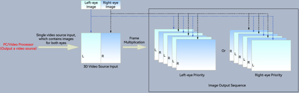
3D imaging is created by the visual depth perceived by our eyes. The distance between the pupils of human eyes is typically around 8cm. When we look at objects, our eyes perceive depth differences, which allows our brain to form 3D images. In order to create the illusion of 3D images for people, it is necessary to present different images to the left and right eyes. This creates a depth gap between the two images, replicating the way our eyes naturally perceive depth. This is how the sensation of 3D stereoscopic vision is achieved.
The COEX series products adopt active shutter 3D technology to be 3D ready. This is achieved by increasing the refresh rate of the screen, splitting the image into two distinct halves for the left and right eyes. These two sets of images are displayed in rapid succession, alternating seamlessly. In tandem, a 3D emitter synchronizes with the 3D glasses via a precise timing signal. This signal ensures that the glasses alternate between blocking each eye, permitting each to view their corresponding images precisely when intended. This process creates stereoscopic 3D images.
¶ 3. COEX System 3D Solution
¶ 3.2 Hardware Setup
| Module | Description |
|---|---|
| 3D Video Source Generating Device | 3D video source generating devices include computers, video processors, and video splicers. These devices are chosen based on factors such as the LED screen size, the input source interface of the controller, and the 3D mode. |
| LED Display Controller |
Single-card controller: MX40 Pro (1G), CX40 Pro (5G) Modular design controller: MX6000 Pro (5G/1G), MX2000 Pro (5G/1G) |
| Receiving Card & LED Screen |
1G receiving cards: Armor series receiving card such as A10s Pro, A10 Plus-N, A8s Pro, A8s-N, A7s Plus, and A5s Plus. 5G receiving cards: CA50E, XA50 Pro |
| 3D Emitter | EMT200 Pro (5G/1G), or third-party emitters. |
| 3D Glasses | MX50. For third-party emitters, please use the corresponding third-party glasses. |
| Control Software | Use VMP to configure LED screen and 3D parameters. |
| Fiber Converter (only required when outputting through optical port) | CVT10 Pro (1G), CVT10 (1G), CVT8-5G (5G) |
Note:
1G/5G refers to the output bandwidth of a single Ethernet port. The MX6000 Pro and MX2000 Pro are modular design controllers, allowing flexible configuration for 1G or 5G output bandwidth control.
- 1G supports 659,722 pixels per port (8bit@60Hz).
- 5G supports 2,951,200 pixels per port (8bit@60Hz).
¶ 3.2 System Topology
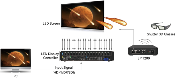
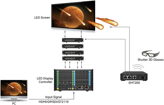
Input the 3D video source into the LED display controller, and then output it to the receiving card, which displays the content on the LED screen. The EMT200 Pro transmits 3D signals, while the 3D glasses detect and receive these signals. By observing the LED screen displaying the 3D video source through the 3D glasses, you can experience the 3D visual effect.
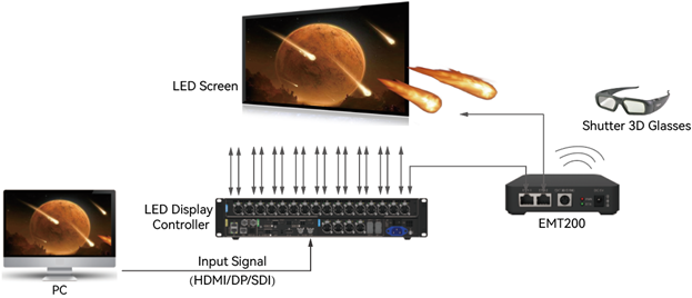
There are two possible connections for the EMT200 Pro within the entire system:
- Connection option 1: The EMT200 Pro is connected behind any receiving card.
- Connection option 2: The EMT200 Pro is connected between the controller and the first receiving card.
Single-card Device (Take MX40 Pro as an example)
Connection option 1
Connection option 2
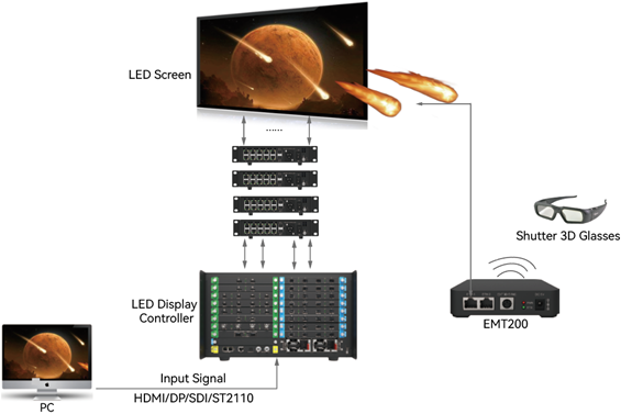
Modular Design Controller (Take MX6000 Pro as an example)
Connection option 1
Connection option 2
¶ 4. 3D Solution Limitations
¶ 4.1 LED Display Controller Limitations
Load Capacity Limitations
The load capacity of a single Ethernet port is reduced by half to 325,000 when the LED display controller is used for 3D projects. The load capacity of each controller after enabling the 3D function is as follows.
| Model | Max Load Capacity | Load Capacity with 3D Enabled |
|
MX40 Pro |
9,000,000 |
4,500,000 |
|
CX40 Pro |
9,000,000 |
4,500,000 |
|
MX6000 Pro |
141,557,760 (A single output card can load up to 17,694,720 pixels. Up to 8 output cards can be installed) |
70,778,880 |
|
MX2000 Pro |
35,389,440 (A single output card can load up to 17,694,720 pixels. Up to 2 output cards can be installed) |
17,694,720 |
Function Limitations
The 3D function and the low latency or frame multiplication function cannot be enabled at the same time.
¶ 4.2 Receiving Card Limitations
| Type | Model | Normal Load Capacity (8bit) | PWM Chip Load Capacity with 3D | Common Chip Load Capacity with 3D | Firmware Version |
| 1G Receiving Card | A10s Pro | 512×512 |
16 groups: 512×256 20 groups: 512×256 24 groups: 512×256 28 groups: 512×256 32 groups: 512×256 |
Common chips are not supported | V1.1.2.0 and later |
| A10s Plus-N | 512×512 | 512×256 | Common chips are not supported | V4.8.0.0 and later | |
| A8s Pro | 512×512 | 512×256 | Common chips are not supported | V1.2.0.0 and later | |
| A8s-N | 512×384 | 256×384 |
Custom program required to support: 192×384 |
V4.6.5.0 and later | |
| A7s Plus | 512×512 | 512×256 | 256×256 | V4.6.2.0 and later | |
| A5s Plus | 512×384 | 256×384 | 192×384 | V4.6.3.0 and later | |
| 5G Receiving Card | CA50E | 512×768 |
16 groups: 512×384 20 groups: 512×384 24 groups: 512×384 28 groups: 512×384 32 groups: 512×384 |
Common chips are not supported | V1.1.2.0 and later |
| XA50 Pro | 512×1024 |
16 groups: 512×512 20 groups: 512×512 24 groups: 512×512 28 groups: 512×512 32 groups: 512×512 |
Common chips are not supported | V1.1.2.0 and later |
Note:
- The load capacity of the receiving card may vary depending on the firmware version. The load capacity listed for each receiving card is for reference purposes only. Please refer to the latest firmware version for the accurate load capacity.
- Please note that when 3D is enabled, certain driver ICs such as ICND2055/2059 and ICND2065/2069 require the Reduced Interframe Space Mode to be enabled in the advanced settings. For driver ICs that do not support Frame Rate Adaptive, a customized firmware program is necessary.
¶ 5. Notes on 3D Function
- Please ensure that the LED display controller and receiving card support the frame rate of 3D output. Specific information can be found in the product specifications.
- When multiple devices are connected in a cascade for splicing and support 3D sources in frame sequential format, it is important to verify the synchronization of the left-eye and right-eye image display between devices. If the display appears abnormal, please adjust the eye priority in VMP.
- When there are multiple 3D video sources input, it is necessary to ensure that the input sources are synchronized.
- For any other inquiries, please contact the FAE of NovaStar for further assistance.
¶ 6. Connector and Indicator Status of 3D Emitter
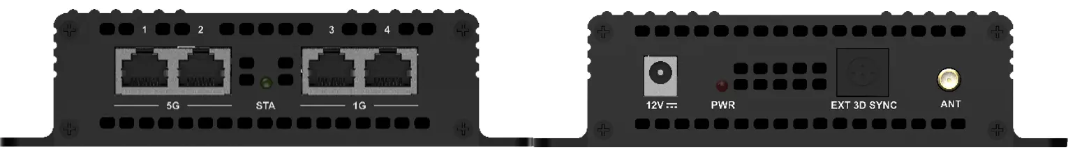
¶ EMT200 Pro (5G/1G)
Appearance
All product pictures shown in this document are for illustration purpose only. Actual product may vary.
Connector
| Name | Description |
|---|---|
| 5G | 5G Ethernet port for signal input or output. |
| 1G | 1G Ethernet port for signal input or output. |
| 12 V | For connecting the supplied power adapter. |
| EXT 3D SYNC | VESA standard connector for connecting a third-party external 3D emitter. |
| ANT | Antenna connector for connecting the supplied antenna. |
Indicator
| Indicator | Color | Status | Description |
|---|---|---|---|
| PWR | Red | Always on | The power input is normal. |
| STA | Green | Flashing once every 1s | The EMT200 Pro is functioning normally. |
| Flashing once every 3s | The EMT200 Pro has no signal input. | ||
| Always on | A third-party external 3D emitter is connected. |
Number of Glasses Supported
| Distance | Number of glasses |
|---|---|
| 70 m | 150 |
| 100 m | 120 |
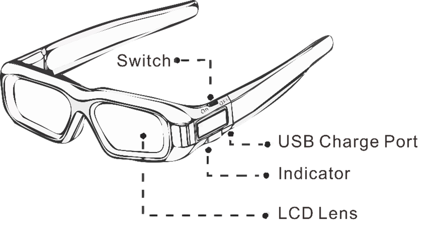
¶ 7. Instructions for MX50 3D Glasses
Appearance
Common Operations
- Turn on the glasses
Set the power switch to ON.
When the green indicator flashes once, the glasses are turned on and will automatically receive 3D signals. When the green indicator remains on for 1 second, the glasses have successfully received 3D signals.
- Standby
Set the power switch to OFF.
- Charging
Connect the USB charge port to a power outlet.
It takes about 2.5 hours to fully charge the 3D glasses. Once fully charged, the 3D glasses can operate continuously for up to 35 hours. Please remember to recharge the glasses after use.
Signal Receiving Range
After turned on, the 3D glasses can detect and receive 3D signals within 30 meters from the EMT200 Pro emitter. After receiving 3D signals, the 3D glasses can operate effectively within a range of 60 meters from the EMT200 Pro emitter.
Note:
When using a third-party emitter and its accompanying 3D glasses, please refer to the respective usage instructions.
¶ 8. Input Source Requirements and Parameter Settings for 3D
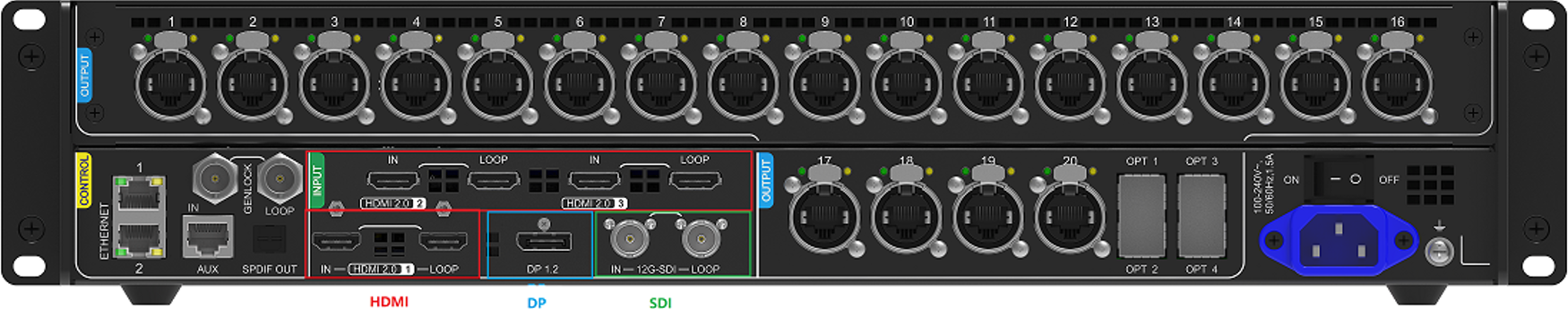
The COEX series products all share the same settings for 3D. This chapter will take the MX40 Pro as an example. The MX40 Pro comes with three types of input source interfaces: HDMI, DP, and SDI. The requirements and parameter settings for the input sources to enable the 3D function are the same across the different types of input source interfaces.
MX40 Pro - Rear Panel
¶ 8.1 Send-Only Controller Mode
This chapter provides an example of using the MX40 Pro in Send-Only Controller mode to enable 3D via the HDMI input interface. There are a total of 9 different setup types that you can refer to, depending on your specific needs.
| No. of Controllers | Example Description |
|
1 unit |
The video source is in side-by-side, top-and-bottom, or frame sequential format. |
|
2 units |
|
¶ Video Source Format
The video source must contain the images intended for both eyes.
- If the video source is in side-by-side format, the width of the video source resolution must be twice that of the LED screen size.
- If the video source is in top-and-bottom format, the height of the video source resolution must be twice that of the LED screen size.
- If the video source is in frame sequential format, the video source resolution must be the same as the LED screen size.
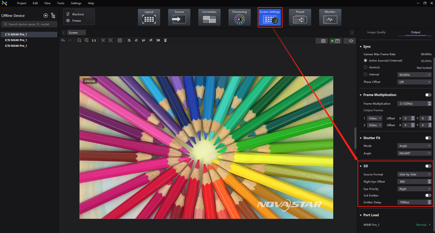
¶ LED Display Controller 3D Parameters
You can configure the 3D parameters via VMP.
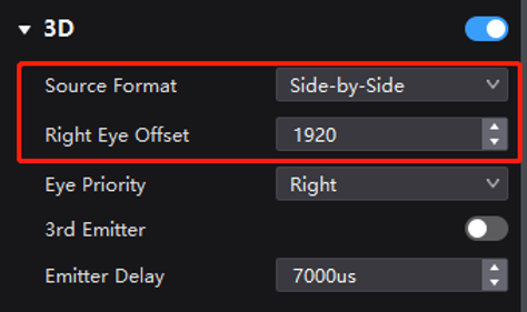
- Source format: Choose the source format based on the video source.
- Right eye offset: This indicates the offset of the right eye image. When the source format is side-by-side, provide the value for x offset. If the source format is top-and-bottom, provide the value for y offset. Please note that this option is grayed out when the source format is frame sequential.
- Eye priority: This option is determined by the timing signal received by the 3D emitter EMT200 Pro for the first time. It should be configured according to the actual effects in the field and does not need to be altered once set.
- 3rd party emitter: Only toggle on this option when using a third-party emitter.
- Note: If you use a third-party emitter, you will still need to connect it to the EMT200 Pro. Refer to 3.2 System Topology for instructions on how to connect the EMT200 Pro. The third-party emitter should be connected to the 3D signal output port of the EMT200 Pro.
- Emitter delay: Usually, the default delay time should be sufficient. However, you can fine-tune its value if the 3D effect doesn't meet the expectations.
Controller 3D settings
¶ 8.1.1 Example 1: 1 Unit of MX40 Pro (in Send-Only Controller Mode) to Achieve 3D Readiness
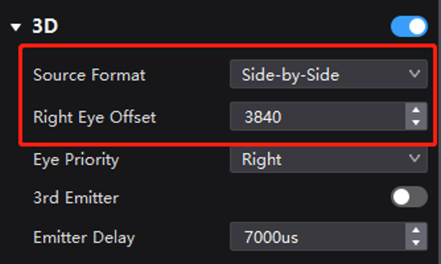
¶ Video Source in Side-by-Side Format
To display 3D content on a 3840×1080 LED screen, a video processor or graphics card is required to deliver a 3D video source with a resolution of 7680×1080 (twice the screen width, comprising images for both eyes) to the HDMI interface of the MX40 Pro.
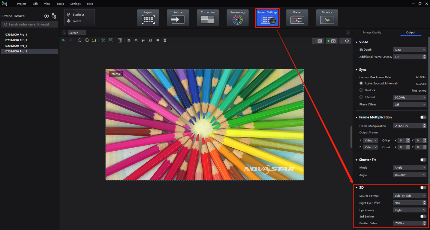
In VMP's Screen Settings interface, enable 3D and then set the Source Format to Side-by-Side. For the Right Eye Offset, you will need to enter the x offset value (since the LED screen has dimensions of 3840×1080, you should set the offset value to 3840.) Don't forget to configure other 3D parameters such as Eye Priority, referring to Figure 5-3.
3D settings (side-by-side format)
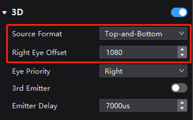
¶ Video Source in Top-and-Bottom Format
To display 3D content on a 3840×1080 LED screen, a video processor or graphics card is required to deliver a 3D video source with a resolution of 3840×2160 (twice the screen height, comprising top and bottom images) to the HDMI interface of the MX40 Pro.
In VMP's Screen Settings interface, enable 3D and then set the Source Format to Top-and-Bottom. For the Right Eye Offset, you will need to enter the y offset value (since the LED screen has dimensions of 3840×1080, you should set the offset value to 1080.) Don't forget to configure other 3D parameters such as Eye Priority, referring to Figure.
3D settings (top-and-bottom format)
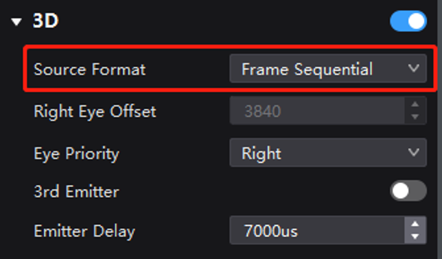
¶ Video Source in Frame Sequential Format
To display 3D content on a 3840×1080 LED screen, a video processor or graphics card is required to deliver a 3D video source with a resolution of 3840×1080 (same as the screen resolution) to the HDMI interface of the MX40 Pro.
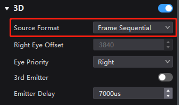
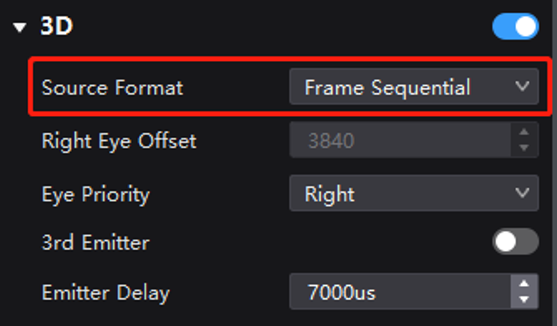
In VMP's Screen Settings interface, enable 3D and then set the Source Format to Frame Sequential. There is no need to set the offset value for video sources in frame sequential format, but don't forget to configure other 3D parameters such as Eye Priority, referring to Figure .
3D settings (frame sequential format)
¶ 8.1.2 Example 2: 2 Units of MX40 Pro (in Send-Only Controller Mode) to Achieve 3D Readiness
¶ Video Source in Side-by-Side Format, with Two Units of MX40 Pro Spliced Side by Side
1. Use two units of MX40 Pro, each loading a screen at a resolution of 3840×1080, and splice them side by side to create a single screen with a resolution of 7680×1080.
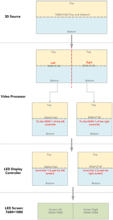
2. Set up the video processor or splicer to crop and splice the 3D source. The goal is to splice the image after cropping, effectively dividing a 15360×1080 image into four parts and then combining them based on the controller position (splicing order detailed below). The end result should yield two 3D sources, each with a resolution of 7680×1080 (twice the width of a single controller's load width), containing respective halves of the left-eye and right-eye images for the intended controller.
3. Feed the 3D sources to the two controllers through the HDMI interfaces. Each MX40 Pro is responsible for loading its corresponding 3D content.
3D source cropping and splicing diagram

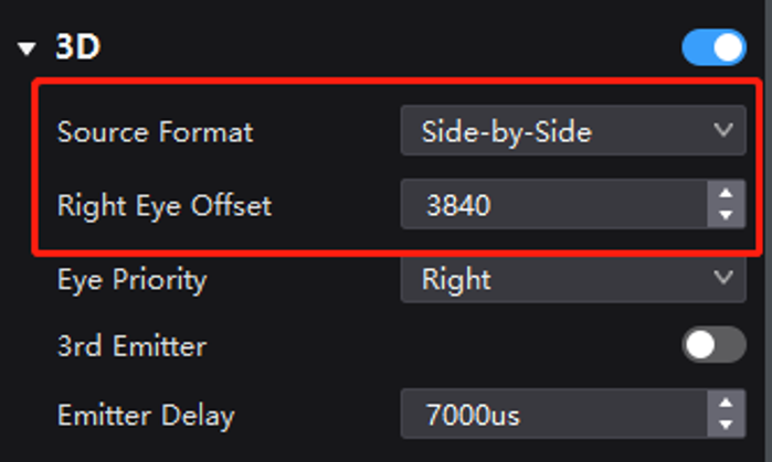
4. In VMP's Screen Settings interface, enable 3D and then set the Source Format to Side-by-Side for both controllers. For the Right Eye Offset, you will need to enter the x offset value (since the LED screen has dimensions of 3840×1080, you should set the offset value to 3840.) Don't forget to configure other 3D parameters such as Eye Priority.
3D settings (side-by-side format)
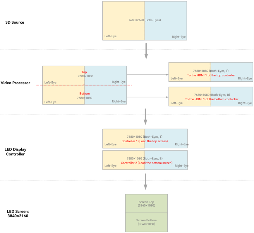
¶ Video Source in Side-by-Side Format, with Two Units of MX40 Pro Spliced Top and Bottom
1. Use two units of MX40 Pro, each loading a screen at a resolution of 3840×1080, and splice them top and bottom to create a single screen with a resolution of 3840×2160.
2. Set up the video processor or splicer to crop and splice the 3D source. The goal is to splice the image after cropping, effectively dividing a 7680×2160 image into two parts and then combining them based on the controller position (splicing order detailed below). The end result should yield two 3D sources, each with a resolution of 7680×1080 (twice the width of a single controller's load width), containing respective halves of the left-eye and right-eye images for the intended controller.
3. Feed the 3D sources to the two controllers through the HDMI interfaces. Each MX40 Pro is responsible for loading its corresponding 3D content.
3D source cropping and splicing diagram
4. In VMP's Screen Settings interface, enable 3D and then set the Source Format to Side-by-Side for both controllers. For the Right Eye Offset, you will need to enter the x offset value (since the LED screen has dimensions of 3840×1080, you should set the offset value to 3840.) Don't forget to configure other 3D parameters such as Eye Priority.
3D settings (side-by-side format)

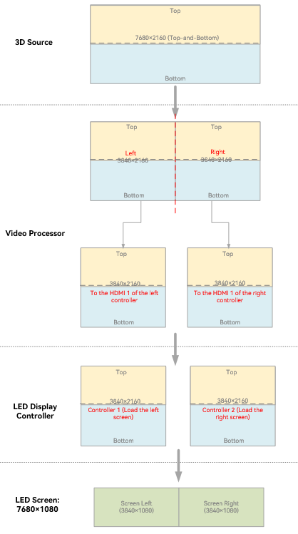
¶ Video Source in Top-and-Bottom Format, with Two Units of MX40 Pro Spliced Side by Side
1. Use two units of MX40 Pro, each loading a screen at a resolution of 3840×1080, and splice them side by side to create a single screen with a resolution of 7680×1080.
2. Set up the video processor or splicer to crop and splice the 3D source. The goal is to splice the image after cropping, effectively dividing a 7680×2160 image into two parts and then combining them based on the controller position (splicing order detailed below). The end result should yield two 3D sources, each with a resolution of 3840×2160 (twice the height of a single controller's load height), containing respective halves of the left-eye and right-eye images for the intended controller.
3. Feed the 3D sources to the two controllers through the HDMI interfaces. Each MX40 Pro is responsible for loading its corresponding 3D content.
3D source cropping and splicing diagram
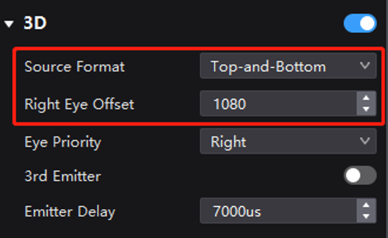
4. In VMP's Screen Settings interface, enable 3D and then set the Source Format to Top-and-Bottom for both controllers. For the Right Eye Offset, you will need to enter the y offset value (since the LED screen has dimensions of 3840×1080, you should set the offset value to 1080.) Don't forget to configure other 3D parameters such as Eye Priority.
3D settings (top-and-bottom format)

¶ Video Source in Top-and-Bottom Format, with Two Units of MX40 Pro Spliced Top and Bottom
1. Use two units of MX40 Pro, each loading a screen at a resolution of 3840×1080, and splice them top and bottom to create a single screen with a resolution of 3840×2160.
2. Set up the video processor or splicer to crop and splice the 3D source. The goal is to splice the image after cropping, effectively dividing a 3840×4320 image into four parts and then combining them based on the controller position (splicing order detailed below). The end result should yield two 3D sources, each with a resolution of 3840×2160 (twice the height of a single controller's load height), containing respective halves of the left-eye and right-eye images for the intended controller.
3. Feed the 3D sources to the two controllers through the HDMI interfaces. Each MX40 Pro is responsible for loading its corresponding 3D content.
3D source cropping and splicing diagram

4. In VMP's Screen Settings interface, enable 3D and then set the Source Format to Top-and-Bottom for both controllers. For the Right Eye Offset, you will need to enter the y offset value (since the LED screen has dimensions of 3840×1080, you should set the offset value to 1080.) Don't forget to configure other 3D parameters such as Eye Priority.
3D settings (top-and-bottom format)
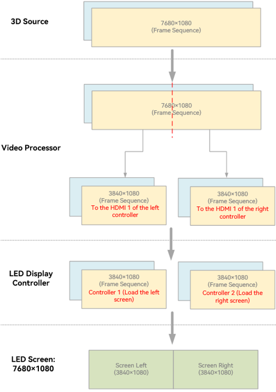
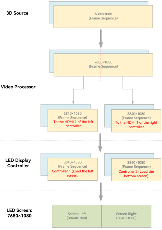
¶ Video Source in Frame Sequential Format, with Two Units of MX40 Pro Spliced Side by Side
1. Use two units of MX40 Pro, each loading a screen at a resolution of 3840×1080, and splice them side by side to create a single screen with a resolution of 7680×1080.
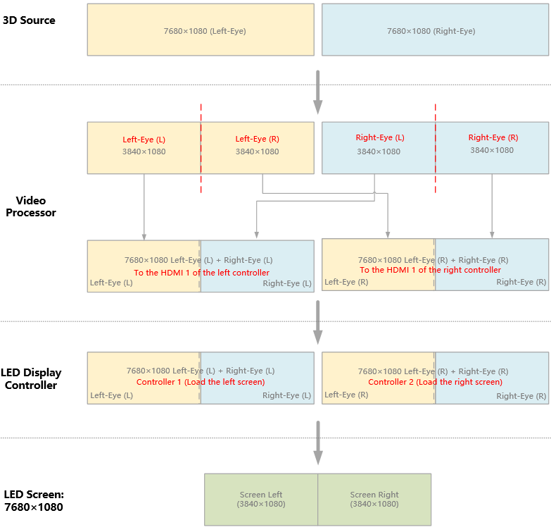
2. Set up the video processor or splicer to crop and splice the 3D source. The goal is to splice the image after cropping, effectively dividing a 7680×1080 image into two parts and then combining them based on the controller position (splicing order detailed below). The end result should yield two 3D sources, each with a resolution of 3840×1080 (same as the resolution of a single controller's load), containing respective halves of the left-eye and right-eye images for the intended controller.
3. Feed the 3D sources to the two controllers through the HDMI interfaces. Each MX40 Pro is responsible for loading its corresponding 3D content.
3D source cropping and splicing diagram
4. In VMP's Screen Settings interface, enable 3D and then set the Source Format to Frame Sequential for both controllers. There is no need to set the offset value for video sources in sequential format, but don't forget to and configure other 3D parameters such as Eye Priority, referring to Figure 5-15.
3D settings (frame sequential format)

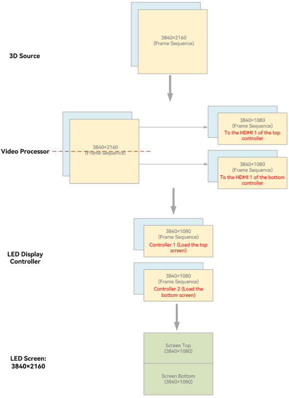
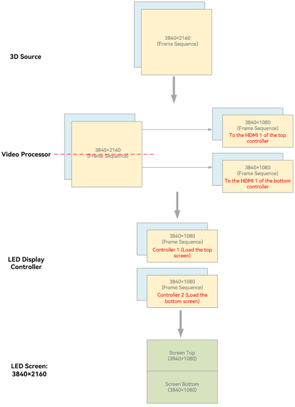
¶ Video Source in Frame Sequential Format, with Two Units of MX40 Pro Spliced Top and Bottom
1. Use two units of MX40 Pro, each loading a screen at a resolution of 3840×1080, and splice them top and bottom to create a single screen with a resolution of 3840×2160.
2. Set up the video processor or splicer to crop and splice the 3D source. The goal is to splice the image after cropping, effectively dividing a 3840×2160 image into two parts and then combining them based on the controller position (splicing order detailed below). The end result should yield two 3D sources, each with a resolution of 3840×1080 (same as the resolution of a single controller's load), containing respective halves of the left-eye and right-eye images for the intended controller.
3. Feed the 3D sources to the two controllers through the HDMI interfaces. Each MX40 Pro is responsible for loading its corresponding 3D content.
3D source cropping and splicing diagram
4. In VMP's Screen Settings interface, enable 3D and then set the Source Format to Frame Sequential for both controllers. There is no need to set the offset value for video sources in sequential format, but don't forget to and configure other 3D parameters such as Eye Priority.
3D settings (frame sequential format)
Note
- The screens in the examples above are evenly spliced. In actual applications, there is no limitation on this. Unevenly spliced screens can still achieve 3D readiness as long as you adjust the 3D settings according to the screen specifications.
- If multiple controllers (all set to Send-Only Controller mode) are being used, follow the same principles outlined in 5.1.2 Example 2: 2 Units of MX40 Pro (in Send-Only Controller Mode) to Achieve 3D Readiness to configure the settings necessary to achieve 3D readiness.
¶ 8.2 All-In-One Controller Mode
The COEX series of LED display controllers offer two working modes. When using the All-in-One Controller mode, it supports video processing functions, which require different settings from the Send-Only Controller mode.
This chapter provides an example of using the MX40 Pro in All-in-One Controller mode to enable 3D via the HDMI input interface. There are a total of 11 different setup types that you can refer to, depending on your specific needs.
| No. of Controllers | Example Description | |
|
1 unit |
The video source is in side-by-side, top-and-bottom, or frame sequential format. |
|
|
2 units |
|
|
|
The video source is in side-by-side format, with the two controllers spliced side by side; the video source is in top-and-bottom format, with the two controllers spliced top and bottom. |
|
¶ Video Source Format
In All-in-One Controller mode, the 3D source will be rescaled to fit the screen size. The source only needs to contain the images intended for both eyes.
¶ LED Display Controller 3D Parameters
You can configure the 3D parameters via VMP. Please refer to Figure.
- Source format: Choose the source format based on the video source.
- Right eye offset: This indicates the offset of the right eye image. When the source format is side-by-side, provide the value for x offset. If the source format is top-and-bottom, provide the value for y offset. Please note that this option is grayed out when the source format is frame sequential.
- Eye priority: This option is determined by the timing signal received by the 3D emitter EMT200 Pro for the first time. It should be configured according to the actual effects in the field and does not need to be altered once set.
- 3rd party emitter: Only toggle on this option when using a third-party emitter.
- Note: If you use a third-party emitter, you will still need to connect it to the EMT200 Pro. Refer to 3.2 System Topology for instructions on how to connect the EMT200 Pro. The third-party emitter should be connected to the 3D signal output port of the EMT200 Pro.
- Emitter delay: Usually, the default delay time should be sufficient. However, you can fine-tune its value if the 3D effect doesn't meet the expectations.
Controller 3D settings
¶ 8.2.1 Example 1: 1 Unit of MX40 Pro (in All-in-One Controller Mode) to Achieve 3D Readiness
¶ Video Source in Side-by-Side Format
To display 3D content on a 3840×1080 LED screen, a video processor or graphics card is required to deliver a 3D video source (which includes images intended for both eyes) to the HDMI interface of the MX40 Pro. The source should have a minimum resolution of 800×600 and a maximum resolution of 8192×1080.
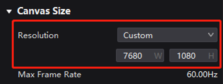
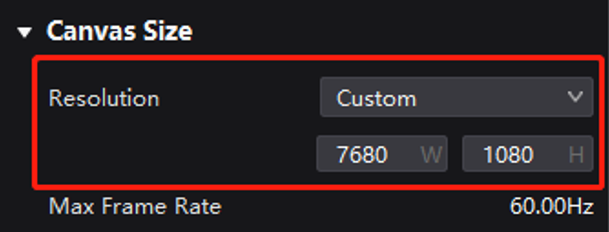
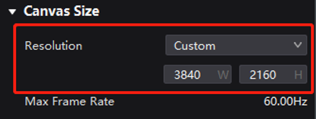
In VMP's Layout interface, set the canvas size to 7680×1080.
Canvas size
Depending on the type of input source, there are two ways to configure the settings.
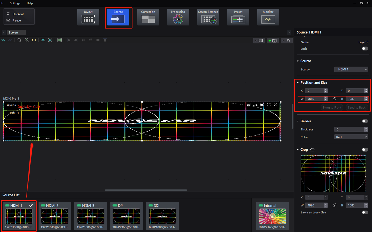
- When the video source is in a side-by-side format and fed to the controller through a single HDMI interface:
In VMP's Source interface, double-click on the HDMI source of the 3D video source to create a layer. Adjust the input source size under Position and Size on the right side of the interface to match the canvas size (7680×1080).
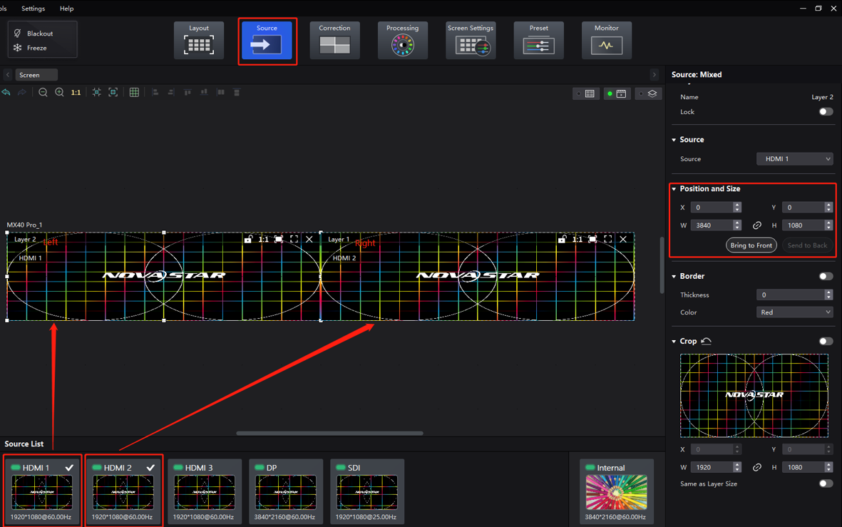
- When the video source is in side-by-side format and fed to the controller via two HDMI interfaces:
In VMP's Source interface, double-click on the HDMI sources of the 3D video sources (left and right eye images) respectively to create two layers. Adjust the input source size under Position and Size on the right side of the interface to match the screen size (3840×1080).
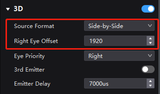
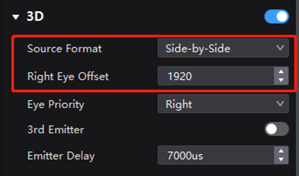
In VMP's Screen Settings interface, enable 3D and then set the Source Format to Side-by-Side. For the Right Eye Offset, you will need to enter the x offset value (since the LED screen has dimensions of 3840×1080, you should set the offset value to 1920.) Don't forget to configure other 3D parameters such as Eye Priority.
3D settings (side-by-side format)

¶ Video Source in Top-and-Bottom Format
To display 3D content on a 3840×1080 LED screen, a video processor or graphics card is required to deliver a 3D video source (which includes images intended for both eyes) to the HDMI interface of the MX40 Pro. The source should have a minimum resolution of 800×600 and a maximum resolution of 8192×1080.
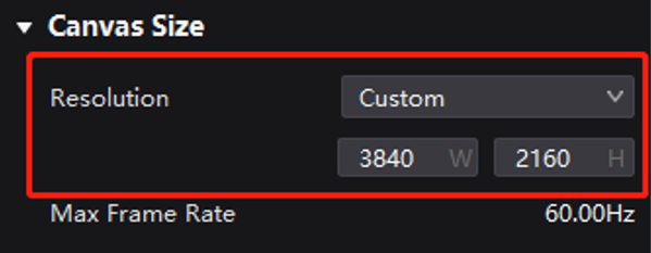
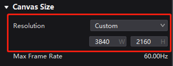
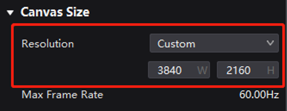
In VMP's Layout interface, set the canvas size to 3840×2160.
Canvas size
Depending on the type of input source, there are two ways to configure the settings.
- When the video source is top-and-bottom format and fed to the controller through a single HDMI interface:
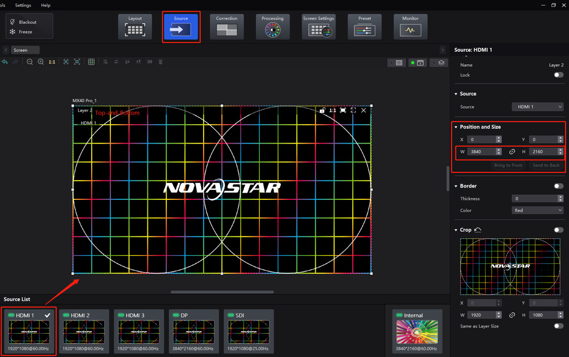
In VMP's Source interface, double-click on the HDMI source of the 3D video source to create a layer. Adjust the input source size under Position and Size on the right side of the interface to match the canvas size (3840×2160).
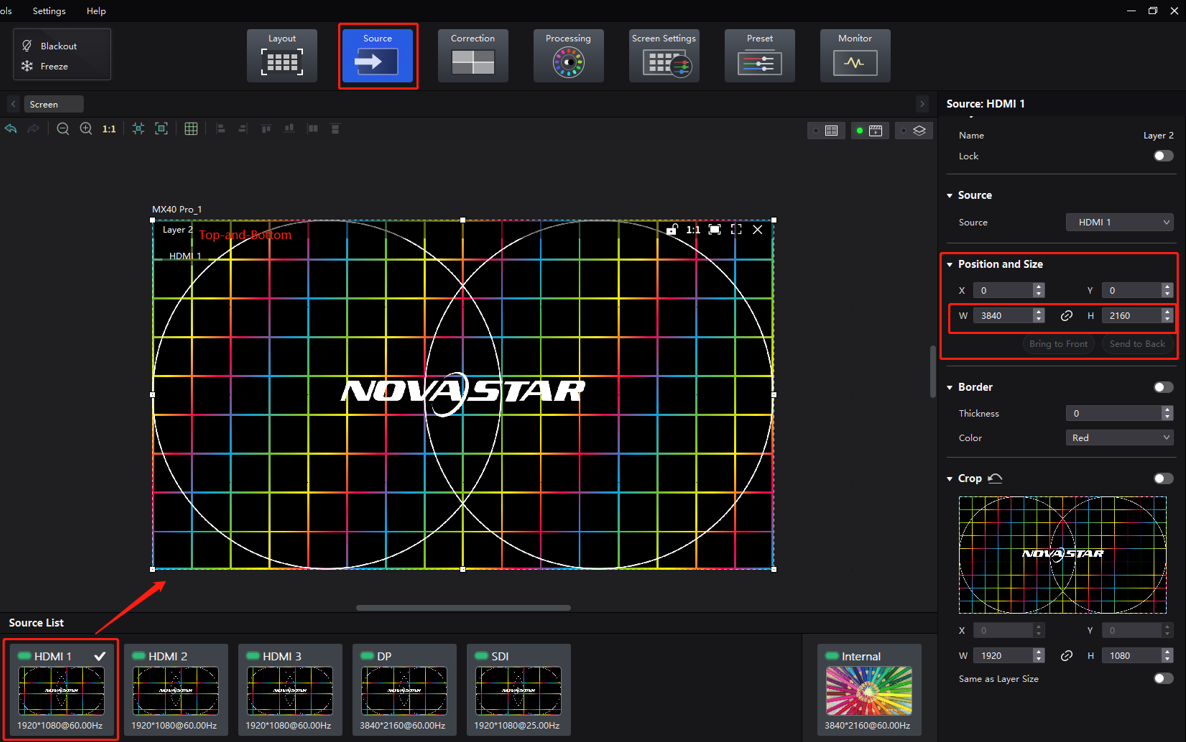
- When the video source is in top-and-bottom format and fed to the controller via two HDMI interfaces:
In VMP's Source interface, double-click on the HDMI sources of the 3D video sources (top and bottom) respectively to create two layers. Adjust the input source size under Position and Size on the right side of the interface to match the screen size (3840×1080).
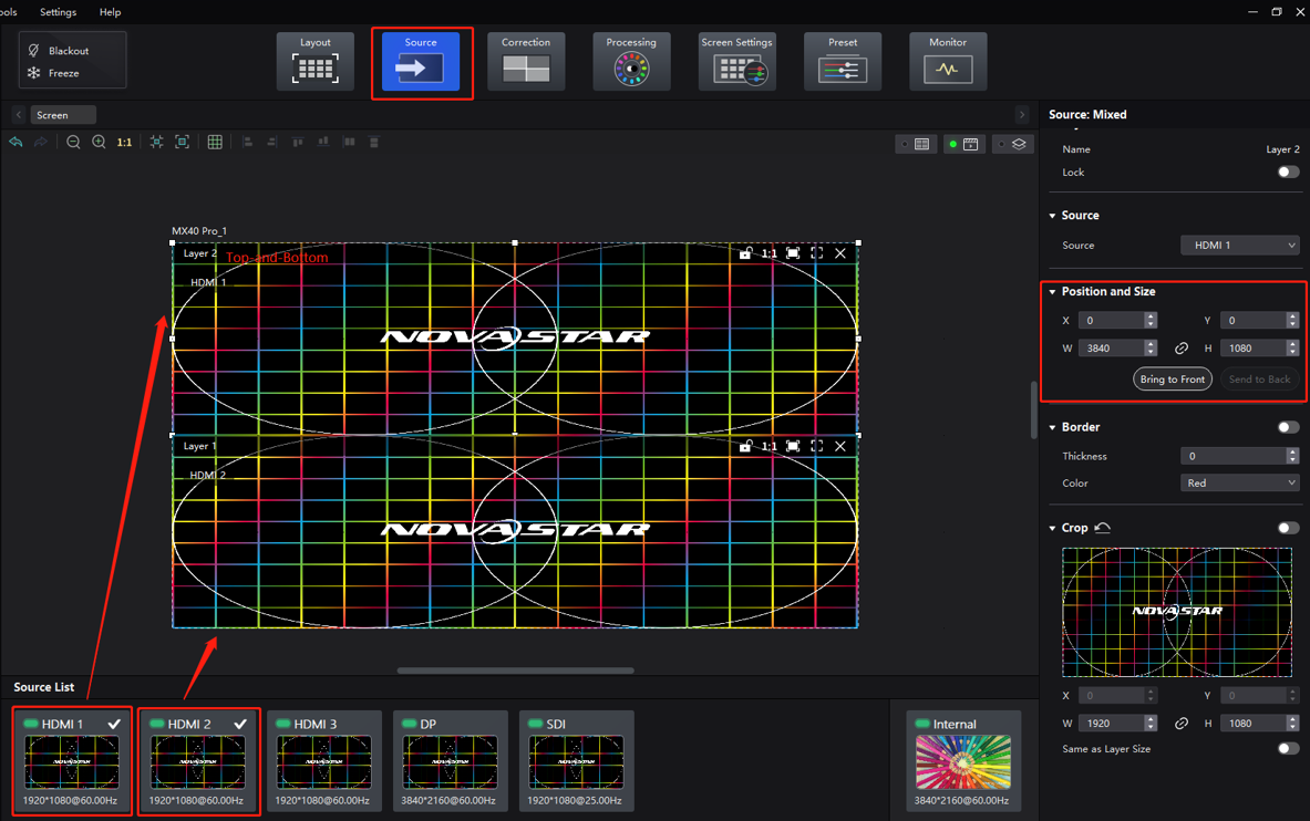
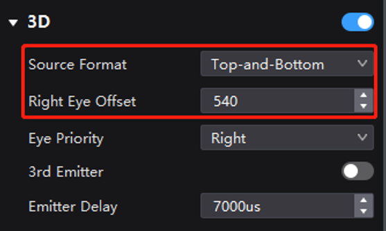
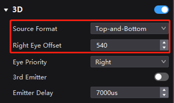
In VMP's Screen Settings interface, enable 3D and then set the Source Format to Top-and-Bottom. For the Right Eye Offset, you will need to enter the y offset value (since the LED screen has dimensions of 3840×1080, you should set the offset value to 540.) Don't forget to configure other 3D parameters such as Eye Priority.
3D settings (top-and-bottom format)

¶ Video Source in Frame Sequential Format
To display 3D content on a 3840×1080 LED screen, a video processor or graphics card is required to deliver a 3D video source (which includes images intended for both eyes) to the HDMI interface of the MX40 Pro. The source should have a minimum resolution of 800×600 and a maximum resolution of 4096×1080.
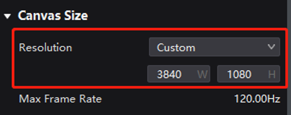
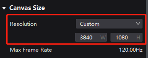
In VMP's Layout interface, set the canvas size to 3840×1080.
Canvas size
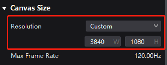
Depending on the type of input source, there are two ways to configure the settings.
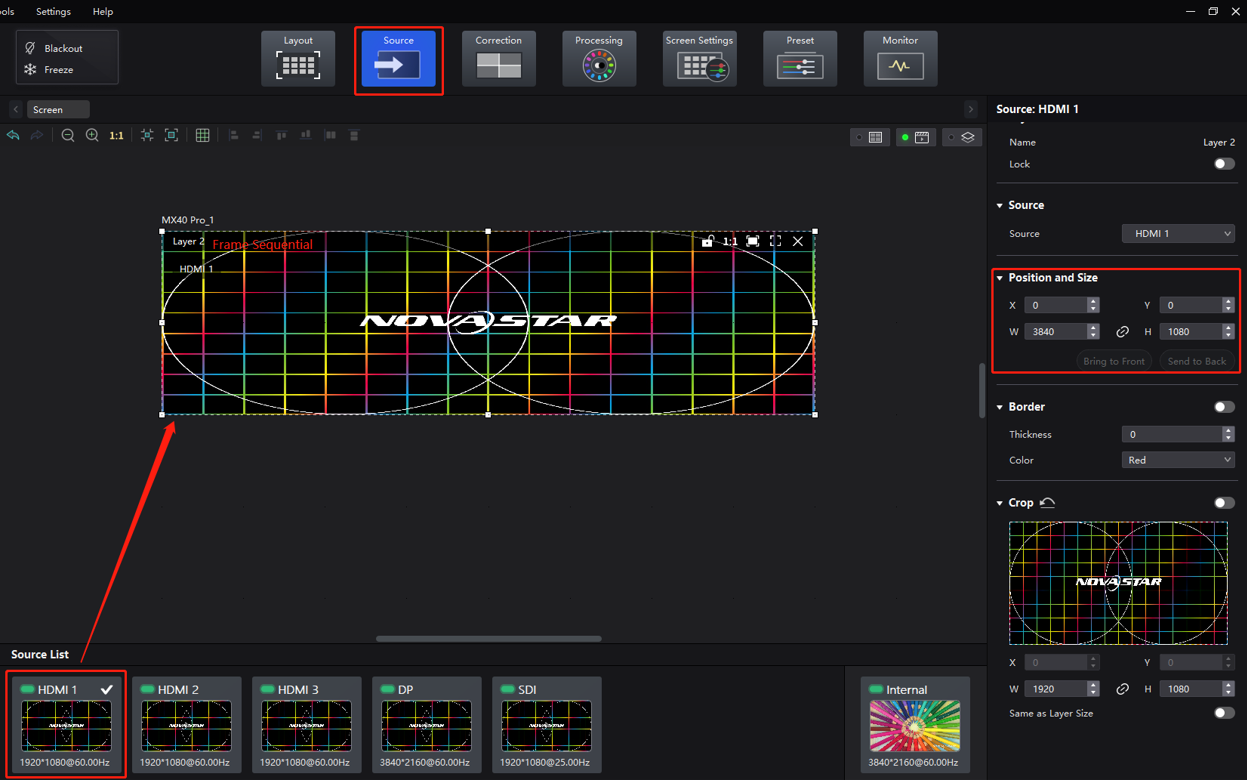
- When the video source is frame sequential format and fed to the controller through a single HDMI interface:
In VMP's Source interface, double-click on the HDMI source of the 3D video source to create a layer. Adjust the input source size under Position and Size on the right side of the interface to match the screen size (3840×1080).

- When the video source is in frame sequential format and fed to the controller via two HDMI interfaces:
In VMP's Source interface, double-click on the HDMI sources of the 3D video sources (alternate frames) respectively to create two layers. Adjust the input source size under Position and Size on the right side of the interface to match the screen size (3840×1080).
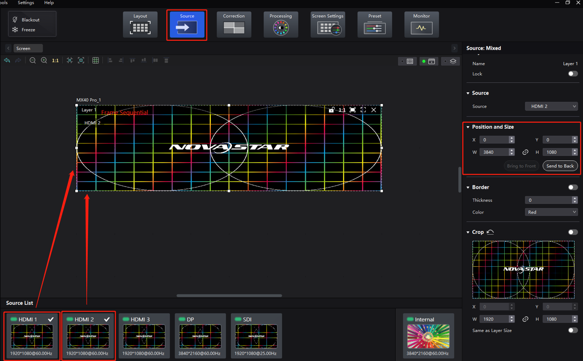
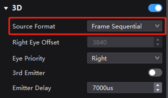
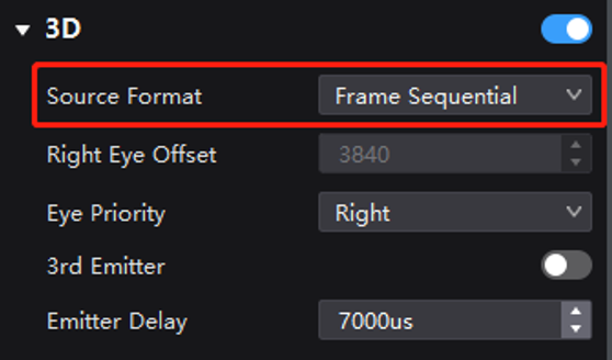
In VMP's Screen Settings interface, enable 3D and then set the Source Format to Frame Sequential. There is no need to set the offset value for video sources in frame sequential format, but don't forget to configure other 3D parameters such as Eye Priority.
3D settings (frame sequential format)
¶ 8.2.2 Example 2: 2 Units of MX40 Pro (in All-in-One Controller Mode) to Achieve 3D Readiness
There are two ways to achieve 3D readiness with 2 units of MX40 Pro in All-in-One Controller mode:
- Method 1: The left and right, or top and bottom images of the 3D video sources in side-by-side or top-and-bottom format are processed and combined based on the loading ratio of each MX40 Pro using a video processor or splicer. For 3D video sources in frame sequential format, they can also be processed according to the loading ratio and then routed to the corresponding MX40 Pro. The settings needed to achieve 3D readiness are the same as those of using a single MX40 Pro.
- Method 2: Feed the 3D video source to HDMI 1 and HDMI 2 of each MX40 Pro using a splitter or other distributors to ensure that each MX40 Pro receives the same synchronized 3D video source. Next, use VMP's cropping and scaling function to achieve screen splicing with two units of MX40 Pro. The settings needed to achieve 3D readiness are the same as those of using a single MX40 Pro.
¶ Method 1: Use a Video Processor or Splicer
¶ Video Source in Side-by-Side Format, with Two Units of MX40 Pro Spliced Side by Side
Use two units of MX40 Pro, each loading a screen at a resolution of 3840×1080, and splice them side by side to create a single screen with a resolution of 7680×1080.
Set up the video processor or splicer to crop and splice the 3D source. The goal is to splice the image after cropping, effectively dividing a 15360×1080 image into four parts and then combining them based on the controller position (splicing order detailed below). The end result should yield two 3D sources containing respective halves of the left-eye and right-eye images for the intended controller. The source should have a minimum resolution of 800×600 and a maximum resolution of 8192×1080.
Feed the 3D sources to the two controllers through the HDMI interfaces. Each MX40 Pro is responsible for loading its corresponding 3D content.
3D source cropping and splicing diagram (using a video processor or splicer)
In VMP's Layout interface, set the canvas size to 7680×1080 for both controllers.
Canvas size
In VMP's Source interface, double-click on the HDMI source of the 3D video source to create a layer. Adjust the input source size under Position and Size on the right side of the interface to match the canvas size (7680×1080).
Adjust input source size

In VMP's Screen Settings interface, enable 3D and then set the Source Format to Side-by-Side. For the Right Eye Offset, you will need to enter the x offset value (since the LED screen has dimensions of 3840×1080, you should set the offset value to 1920.) Don't forget to configure other 3D parameters such as Eye Priority.
3D settings (side-by-side format)
¶ Video Source in Side-by-Side Format, with Two Units of MX40 Pro Spliced Top and Bottom
Use two units of MX40 Pro, each loading a screen at a resolution of 3840×1080, and splice them top and bottom to create a single screen with a resolution of 3840×2160.
Set up the video processor or splicer to crop and splice the 3D source. The goal is to splice the image after cropping, effectively dividing a 7680×2160 image into two parts and then combining them based on the controller position (splicing order detailed below). The end result should yield two 3D sources containing respective halves of the left-eye and right-eye images for the intended controller. The source should have a minimum resolution of 800×600 and a maximum resolution of 8192×1080.
Feed the 3D sources to the two controllers through the HDMI interfaces. Each MX40 Pro is responsible for loading its corresponding 3D content.
3D source cropping and splicing diagram (using a video processor or splicer)

In VMP's Layout interface, set the canvas size to 7680×1080 for both controllers.
Canvas size

In VMP's Source interface, double-click on the HDMI source of the 3D video source to create a layer. Adjust the input source size under Position and Size on the right side of the interface to match the canvas size (7680×1080).
Adjust input source size

In VMP's Screen Settings interface, enable 3D and then set the Source Format to Side-by-Side. For the Right Eye Offset, you will need to enter the x offset value (since the LED screen has dimensions of 3840×1080, you should set the offset value to 1920.) Don't forget to configure other 3D parameters such as Eye Priority.
3D settings (side-by-side format)
¶ Video Source in Top-and-Bottom Format, with Two Units of MX40 Pro Spliced Side by Side
Use two units of MX40 Pro, each loading a screen at a resolution of 3840×1080, and splice them side by side to create a single screen with a resolution of 7680×1080.
Set up the video processor or splicer to crop and splice the 3D source. The goal is to splice the image after cropping, effectively dividing a 7680×2160 image into two parts and then combining them based on the controller position (splicing order detailed below). The end result should yield two 3D sources containing respective halves of the left-eye and right-eye images for the intended controller. The source should have a minimum resolution of 800×600 and a maximum resolution of 8192×1080.
Feed the 3D sources to the two controllers through the HDMI interfaces. Each MX40 Pro is responsible for loading its corresponding 3D content.
3D source cropping and splicing diagram (using a video processor or splicer)
In VMP's Layout interface, set the canvas size to 3840×2160 for both controllers.
Canvas size
In VMP's Source interface, double-click on the HDMI source of the 3D video source to create a layer. Adjust the input source size under Position and Size on the right side of the interface to match the canvas size (3840×2160).
Adjust input source size

In VMP's Screen Settings interface, enable 3D and then set the Source Format to Top-and-Bottom. For the Right Eye Offset, you will need to enter the y offset value (since the LED screen has dimensions of 3840×1080, you should set the offset value to 540.) Don't forget to configure other 3D parameters such as Eye Priority.
3D settings (top-and-bottom format)
¶ Video Source in Top-and-Bottom Format, with Two Units of MX40 Pro Spliced Top and Bottom
Use two units of MX40 Pro, each loading a screen at a resolution of 3840×1080, and splice them top and bottom to create a single screen with a resolution of 3840×2160.
Set up the video processor or splicer to crop and splice the 3D source. The goal is to splice the image after cropping, effectively dividing a 3840×4320 image into four parts and then combining them based on the controller position (splicing order detailed below). The end result should yield two 3D sources containing respective halves of the left-eye and right-eye images for the intended controller. The source should have a minimum resolution of 800×600 and a maximum resolution of 8192×1080.
Feed the 3D sources to the two controllers through the HDMI interfaces. Each MX40 Pro is responsible for loading its corresponding 3D content.
3D source cropping and splicing diagram (using a video processor or splicer)
In VMP's Layout interface, set the canvas size to 3840×2160 for both controllers.
Canvas size
In VMP's Source interface, double-click on the HDMI source of the 3D video source to create a layer. Adjust the input source size under Position and Size on the right side of the interface to match the canvas size (3840×2160).
Adjust input source size
In VMP's Screen Settings interface, enable 3D and then set the Source Format to Top-and-Bottom. For the Right Eye Offset, you will need to enter the y offset value (since the LED screen has dimensions of 3840×1080, you should set the offset value to 540.) Don't forget to configure other 3D parameters such as Eye Priority.
3D settings (top-and-bottom format)
¶ Video Source in Frame Sequential Format, with Two Units of MX40 Pro Spliced Side by Side
Use two units of MX40 Pro, each loading a screen at a resolution of 3840×1080, and splice them side by side to create a single screen with a resolution of 7680×1080.
Set up the video processor or splicer to crop and splice the 3D source. The goal is to splice the image after cropping, effectively dividing a 7680×1080 image into two parts and then combining them based on the controller position (splicing order detailed below). The end result should yield two 3D sources containing respective halves of the left-eye and right-eye images for the intended controller. The source should have a minimum resolution of 800×600 and a maximum resolution of 4096×1080.
Feed the 3D sources to the two controllers through the HDMI interfaces. Each MX40 Pro is responsible for loading its corresponding 3D content.
3D source cropping and splicing diagram (using a video processor or splicer)
In VMP's Layout interface, set the canvas size to 3840×1080 for both controllers.
Canvas size
In VMP's Source interface, double-click on the HDMI source of the 3D video source to create a layer. Adjust the input source size under Position and Size on the right side of the interface to match the screen size (3840×1080).
Adjust input source size
In VMP's Screen Settings interface, enable 3D and then set the Source Format to Frame Sequential for both controllers. There is no need to set the offset value for video sources in sequential format, but don't forget to and configure other 3D parameters such as Eye Priority.
3D settings (frame sequential format)
¶ Video Source in Frame Sequential Format, with Two Units of MX40 Pro Spliced Top and Bottom
Use two units of MX40 Pro, each loading a screen at a resolution of 3840×1080, and splice them top and bottom to create a single screen with a resolution of 3840×2160.
Set up the video processor or splicer to crop and splice the 3D source. The goal is to splice the image after cropping, effectively dividing a 3840×2160 image into two parts and then combining them based on the controller position (splicing order detailed below). The end result should yield two 3D sources containing respective halves of the left-eye and right-eye images for the intended controller. The source should have a minimum resolution of 800×600 and a maximum resolution of 4096×1080.
Feed the 3D sources to the two controllers through the HDMI interfaces. Each MX40 Pro is responsible for loading its corresponding 3D content.
3D source cropping and splicing diagram (using a video processor or splicer)
In VMP's Layout interface, set the canvas size to 3840×1080 for both controllers.
Canvas size
In VMP's Source interface, double-click on the HDMI source of the 3D video source to create a layer. Adjust the input source size under Position and Size on the right side of the interface to match the screen size (3840×1080).
Adjust input source size

In VMP's Screen Settings interface, enable 3D and then set the Source Format to Frame Sequential for both controllers. There is no need to set the offset value for video sources in sequential format, but don't forget to and configure other 3D parameters such as Eye Priority.
3D settings (frame sequential format)
¶ Method 2: Use VMP
¶ Video Source in Side-by-Side Format, with Two Units of MX40 Pro Spliced Side by Side
Use two units of MX40 Pro, each loading a screen at a resolution of 3840×1080, and splice them side by side to create a single screen with a resolution of 7680×1080.
Feed the 3D video source to the HDMI 1 and HDMI 2 interfaces of both units of MX40 Pro. The source should have a minimum resolution of 800×600 and a maximum resolution of 8192×1080 and contain the images intended for both eyes.
In VMP's Layout interface, set the canvas size to 7680×1080 for both controllers.
Canvas size

In VMP's Source interface, crop and splice the 3D source of HDMI 1 and HDMI 2 based on the controller position (splicing order detailed below). Each MX40 Pro is responsible for loading its corresponding 3D content.
3D source cropping and splicing diagram (using VMP)
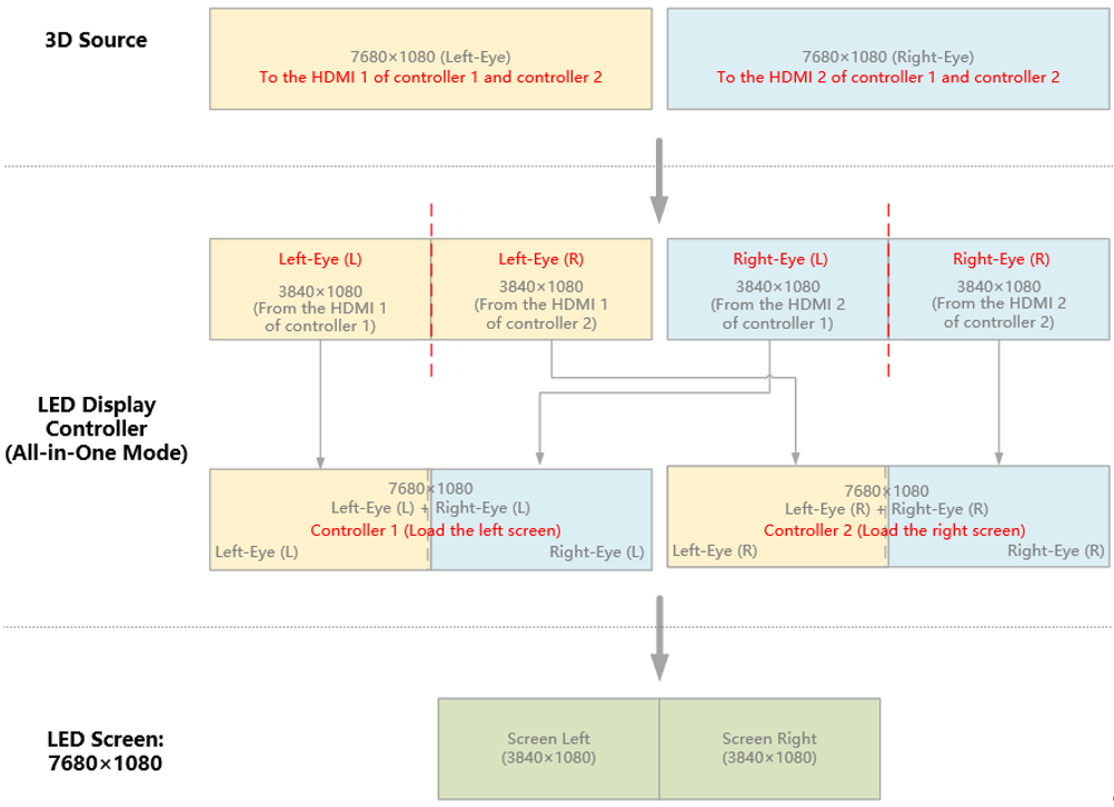
MX40 Pro 1: Load the screen on the left
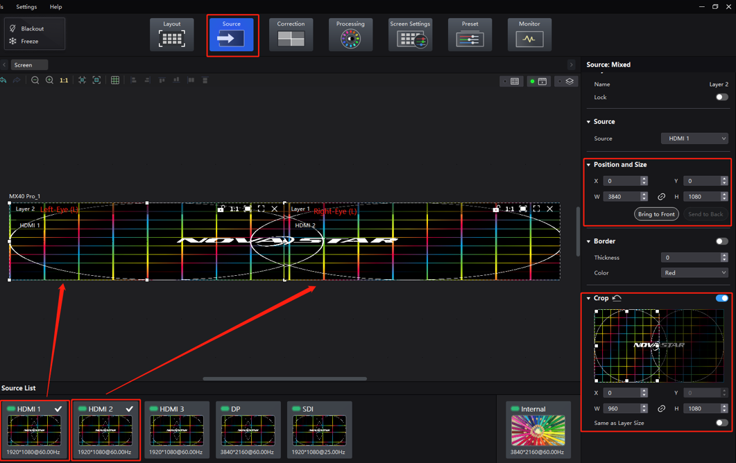
MX40 Pro 2: Load the screen on the right
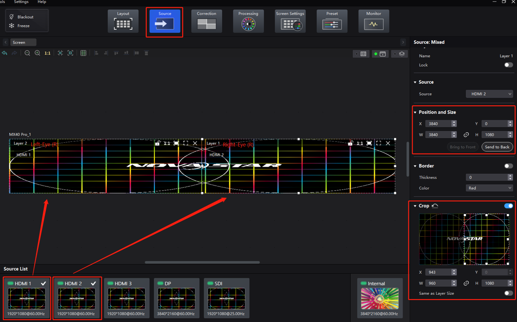
In VMP's Screen Settings interface, enable 3D and then set the Source Format to Side-by-Side. For the Right Eye Offset, you will need to enter the x offset value (since the LED screen has dimensions of 3840×1080, you should set the offset value to 1920.) Don't forget to configure other 3D parameters such as Eye Priority.
3D settings (side-by-side format)
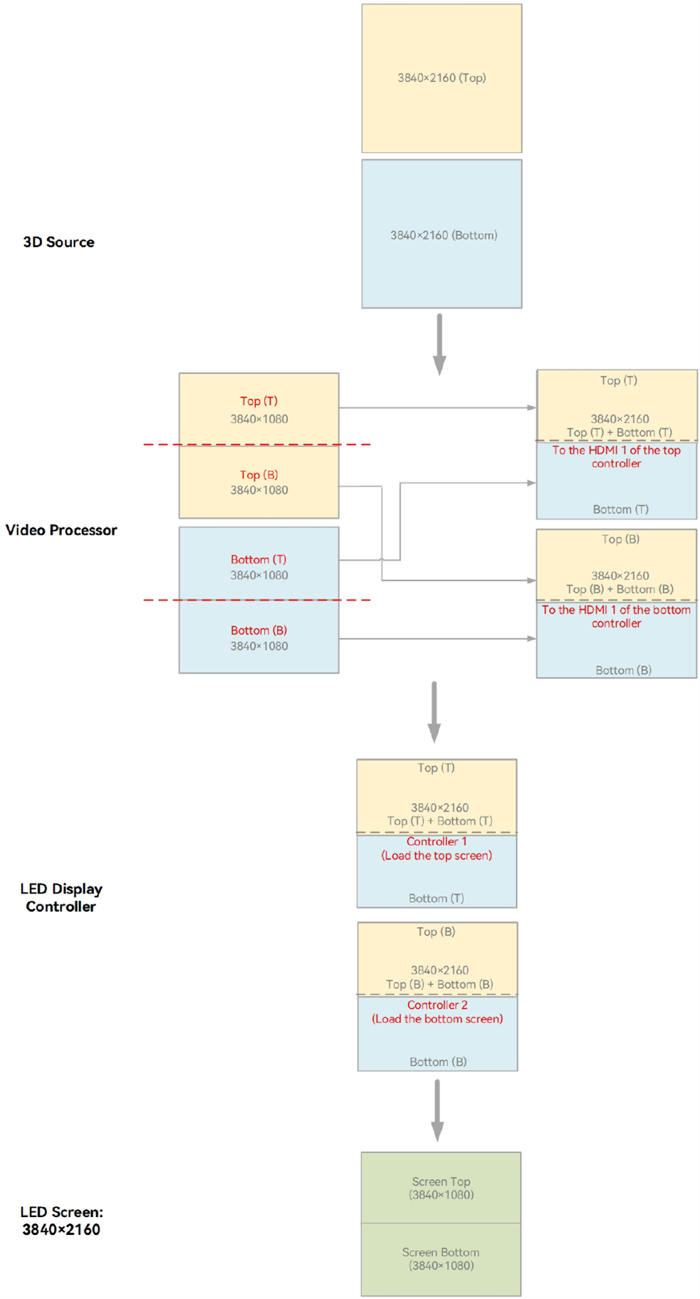
¶ Video Source in Top-and-Bottom Format, with Two Units of MX40 Pro Spliced Top and Bottom
Use two units of MX40 Pro, each loading a screen at a resolution of 3840×1080, and splice them top and bottom to create a single screen with a resolution of 3840×2160.
Feed the 3D video source to the HDMI 1 and HDMI 2 interfaces of both units of MX40 Pro. The source should have a minimum resolution of 800×600 and a maximum resolution of 8192×1080 and contain the images intended for both eyes.
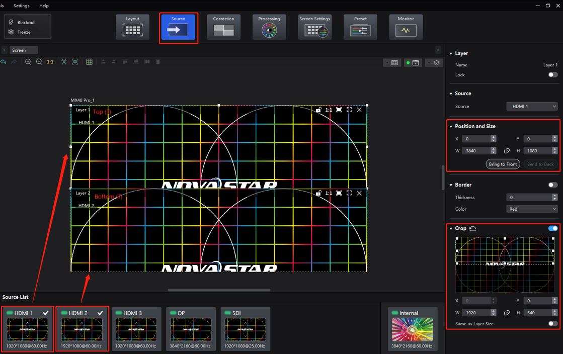
In VMP's Layout interface, set the canvas size to 3840×2160 for both controllers.
Canvas size
In VMP's Source interface, crop and splice the 3D source of HDMI 1 and HDMI 2 based on the controller position (splicing order detailed below). Each MX40 Pro is responsible for loading its corresponding 3D content.
3D source cropping and splicing diagram (using VMP)
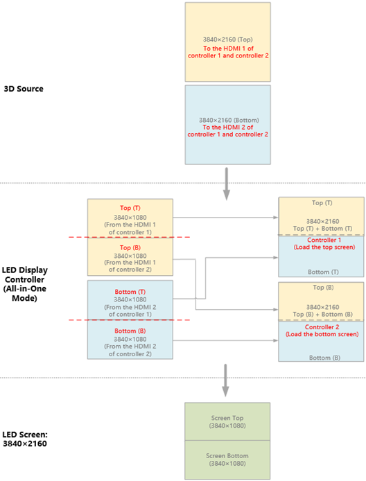
MX40 Pro 1: Load the screen on the top
MX40 Pro 2: Load the screen on the bottom
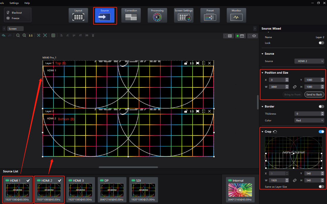
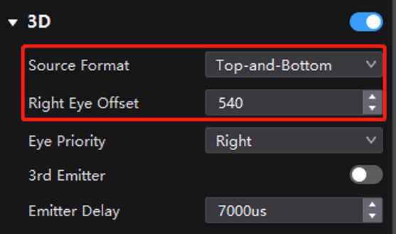
In VMP's Screen Settings interface, enable 3D and then set the Source Format to Top-and-Bottom. For the Right Eye Offset, you will need to enter the y offset value (since the LED screen has dimensions of 3840×1080, you should set the offset value to 540.) Don't forget to configure other 3D parameters such as Eye Priority.
3D settings (top-and-bottom format)
Note
- The screens in the examples above are evenly spliced. In actual applications, there is no limitation on this. Unevenly spliced screens can still achieve 3D readiness as long as you adjust the 3D settings according to the screen specifications.
- If multiple controllers (all set to All-in-One Controller mode) are being used, follow the same principles outlined in 5.2.2 Example 2: 2 Units of MX40 Pro (in All-in-One Controller Mode) to Achieve 3D Readiness to configure the settings necessary to achieve 3D readiness.
We consistently enhance and refine the content of our Wiki articles.
If you find any mistakes or errors, please contact us.
Your continuous feedback and support will help us further improve our products and content.