¶ 1. xR & VP
¶ 1.1 Background
In traditional film and television production, in addition to shooting real scenes, professionals often use another indoor shooting technique—green screen. However, this technique can pose several significant problems:
- Actors cannot fully immerse themselves in the scene, which can be very challenging for their acting skills.
- Post-production costs are too expensive, with rendering usually charged per frame.
- Traditional methods of filming suffer from a notable lack of efficiency. In many cases, seemingly minor setbacks - such as dissatisfaction with certain shots or scenes - can quickly balloon into significant complications, leading to extended shooting cycles and inflated costs.
In light of these issues, it's no wonder that xR virtual shooting technology has gained significant momentum in recent years. With the capacity to bypass the traditional green screen technique and replace it with LED screens, professionals can enjoy a convenient and immersive WYSIWYG (what you see is what your get) shooting experience, greatly reducing the hassles of post-production. As such, xR virtual shooting is becoming more and more widely used in the fields of film and television shooting, TV program production, advertising, web-based content creation, and visual creativity.
¶ 1.2 Introduction
xR, short for Extended Reality, is a technology that combines VR (Virtual Reality), AR (Augmented Reality), and MR (Mixed Reality). It uses computer image rendering engines to display virtual scenes in real-time on LED screens, and with the help of actors and props, it can create unlimited visuals in a limited space through camera tracking and shutter fit technologies, without the need for real outdoor scenes or green screens.
Compared to traditional shooting or green screen shooting, xR virtual shooting has the following advantages:
- Improved shooting quality
xR technology provides an immersive shooting experience for directors and actors, allowing them to see what they're shooting in real-time and delivering more realistic performances, ultimately improving the overall quality of the film.
- Reduced post-production costs
xR technology allows for rapid scene switching and real-time adjustment and modification of scene content without space/time limitations. This greatly improves the efficiency of scene changes, reducing post-production costs.
- Boosted shooting efficiency
Thanks to the rapidly improving LED display technology and continuously advancing software rendering capabilities, xR technology presents an exciting opportunity to streamline post-production workload and expedite the production cycle, ultimately resulting in significantly increased efficiency.
¶ 1.3 End-to-End Topology
xR virtual shooting end-to-end topology
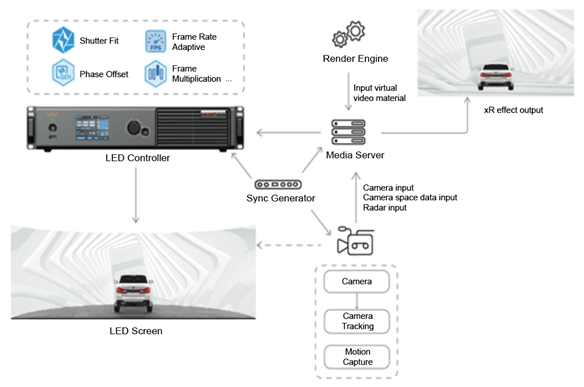
xR Configuration List
| Module | Function |
|
LED Screen |
A background screen that typically requires features such as a wide color gamut, high grayscale, zero color difference in its LEDs, large visibility range and decent mask shading capability. |
|
LED Controller |
The LED controller receives the virtual images transmitted from the media server and outputs them to the LED screen. It requires a sophisticated and cutting-edge video processing technology that is capable of delivering impeccable color fidelity and precise grayscale adjustments necessary to elevate the display performance of the LED screen. Additionally, it necessitates extended support for crucial functionalities such as shutter fit, phase offset, and frame multiplication, enabling the video processing system to tackle common challenges that plague camera-based systems - scan lines and color deviations - with utmost efficiency. |
|
xR Media Server |
The media server includes hardware and software platforms. It creates a live model on the 3D software platform, integrates various video signals, including signals from the camera tracking system, signals provided by the rendering engine, etc., and outputs them after video synthesis, achieving the final xR effect. |
|
Camera |
A camera in the real space, it needs to support the Genlock interface. If multiple cameras are used for shooting, the camera needs to support the initial phase adjustment function. |
| Camera Tracking System | It maps the (x,y,z) coordinates data of the camera in real shooting to the 3D modeling platform for synchronizing the virtual camera. |
| Motion Capture System | A tracking system for the AR foreground object in the rendering engine. For example, when an actor opens his hand and lights up a fire, it is the system's job to define the position of the fire. |
| Real-time Render Engine | It can render video content based on the movement of the camera in the three-dimensional space, which is then transmitted to the media server for integration and output. |
| Sync Signal Generator | It connects various systems on-site (LED control system, shooting system, rendering system, etc.) into a common signal synchronization system to ensure the synchronization of system signals. |
¶ 1.4 Analysis of xR Virtual Shooting
The most fundamental difference between xR virtual shooting and traditional screens is that xR screen is designed for machines, while ordinary screens are mostly designed for humans. Therefore, the performance of LED screens in the camera lens is particularly important in xR applications.
Existing xR problems and requirements for LED systems
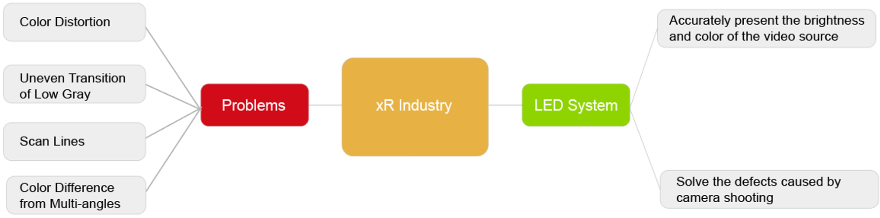
- Color Distortion
The color gamut of LED screens currently has no industry standards, so different LEDs could have different color gamut performances. However, many films are produced based on the standard color gamut, such as BT.709 for the LCD industry, DCI-P3 for the cinema industry, and BT.2020 for HDR standards. Therefore, the color gamut of most LED screens does not match the source, causing the video played on the LED screen to have color deviation, and the color effect of the photographed footage does not match what is seen on the monitor.
- Uneven Transition of Low Gray
When the LED screen does not have enough gray levels, it will cause contours and uneven transitions in low gray images. The non-linear response of the low-grayscale will also cause inaccurate colors and the appearance of contours.
- Scan Lines
Generally, when the camera shoots the display screen, because the sensing unit of the camera performs line-by-line exposure, it does not capture the entire scanning area of the LED screen, resulting in dark lines or bands when images are merged.
- Color Difference from Multi-angles
Due to differences in the light flux of LEDs from different angles, and the different shapes of xR screens such as 90 degrees corner screens, sky screens, and floor tile screens, the color and brightness of the screens seen from the same angle may differ from each other.
To address these issues, the LED control system needs to meet the following requirements:
- Ability to accurately present the brightness and color of the video source.
- Capable of solving the defects caused by camera shooting such as scan lines, inaccurate color, etc.
¶ 2. LED Control System Solution
Based on the characteristics of xR virtual shooting, Xi'an NovaStar Tech Co., Ltd. (hereinafter referred to as NovaStar) has unveiled its trailblazing COEX control system solution to cater expressly to the specifications of virtual shooting and boasts a unique suite of image-enhancing technologies. The solution deftly eradicates vexing issues such as pesky scan lines, color deviation, and loss of details. As a result, the images are imbued with a crystal clearness of detail and true-to-life color fidelity, culminating in stunningly precise and lifelike shooting outcomes, paving the way for genuinely immersive "what you see is what you get" shooting experiences. On top of that, with NovaStar's VMP (Vision Management Platform), the solution combines the quaternity of design, debugging, management, and monitoring into one package. Managing the display system has never been this efficient and convenient.
¶ 2.1 COEX Solution Introduction
LED Screen Diagram
The COEX control system solution can cover the entire process from shipment to installation of the screen, and the following diagram illustrates the support provided by COEX in each stage.
- Diagram of COEX - LED screen
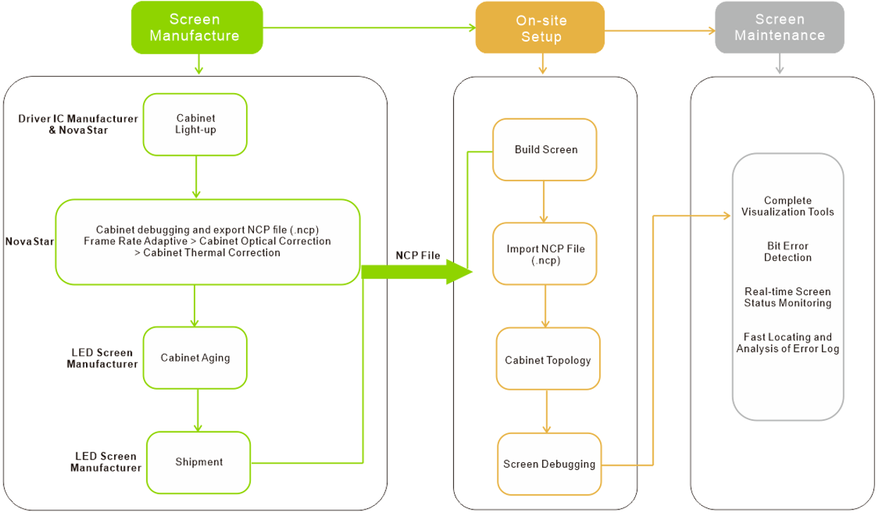
About NCP Files
- To fully use the functionalities of the NovaStar COEX control system, it is necessary to ensure that the debugging process is completed and the cabinet library file (.ncp) is generated before the screen leaves the factory. The debugging process includes driver IC basic illumination test, frame rate adaptive configuration, cabinet optical correction (image booster), and cabinet thermal correction (thermal compensation), of which cabinet thermal correction can be performed as needed.
- NCP file combines the cabinet configuration file, firmware program, screen calibration data, and screen temperature data into one file for management. Users can easily manage the entire process of screen configuration using the NCP file on-site.
- To generate the NCP file, contact NovaStar technical engineers before the screen leaves the factory.
Solution Topology
- COEX - LED Control System Topology
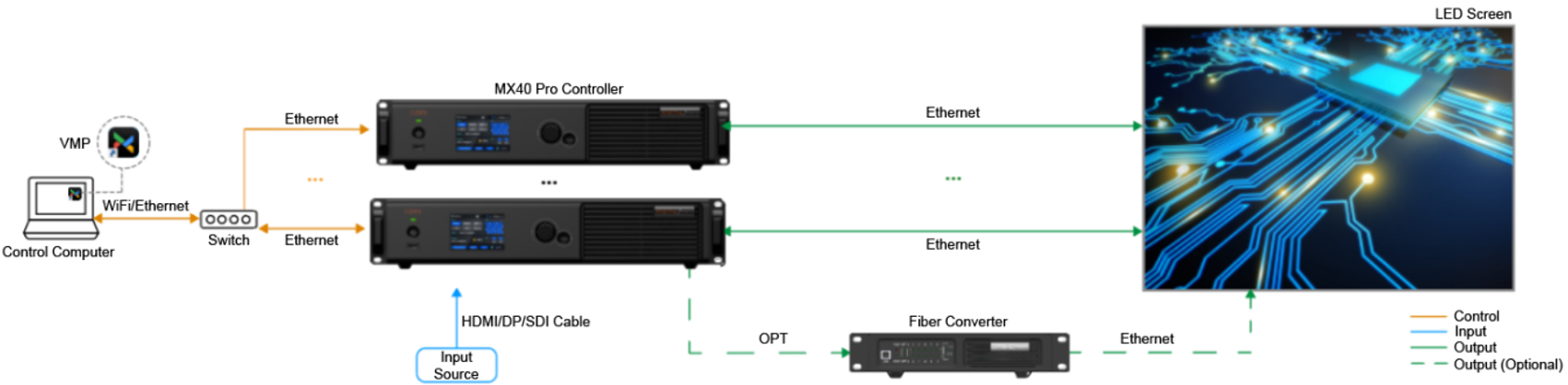
Device list of COEX system
| Module | Description |
|
Control Software |
VMP |
|
LED Display Controller |
MX40 Pro (1G), CX40 Pro (5G), MX6000 Pro (1G/5G), MX2000 Pro (1G/5G) |
|
Receiving Card |
A10s Pro (1G), CA50E (5G) |
|
Fiber Converter (Long-distance Transmission) |
CVT10 Pro (1G), CVT8-5G (5G) |
Note:
The 1G/5G in the table refers to the output bandwidth of a single Ethernet port. The MX6000 Pro and MX2000 Pro are card-based devices that can be flexibly configured to control systems with either 1G or 5G output bandwidth.
- 1G: a single port loads 659,722 pixels (8bit@60Hz).
- 5G: a single port loads 2,951,200 pixels (8bit@60Hz).
For more details, please refer to 3.2 COEX Single-Card Controller Specifications / 3.3 COEX Card-Based Controller Specifications.
¶ 2.2 Image Boosting
¶ Image Booster
Overview
Image booster can enhance the display effect via the following three methods:
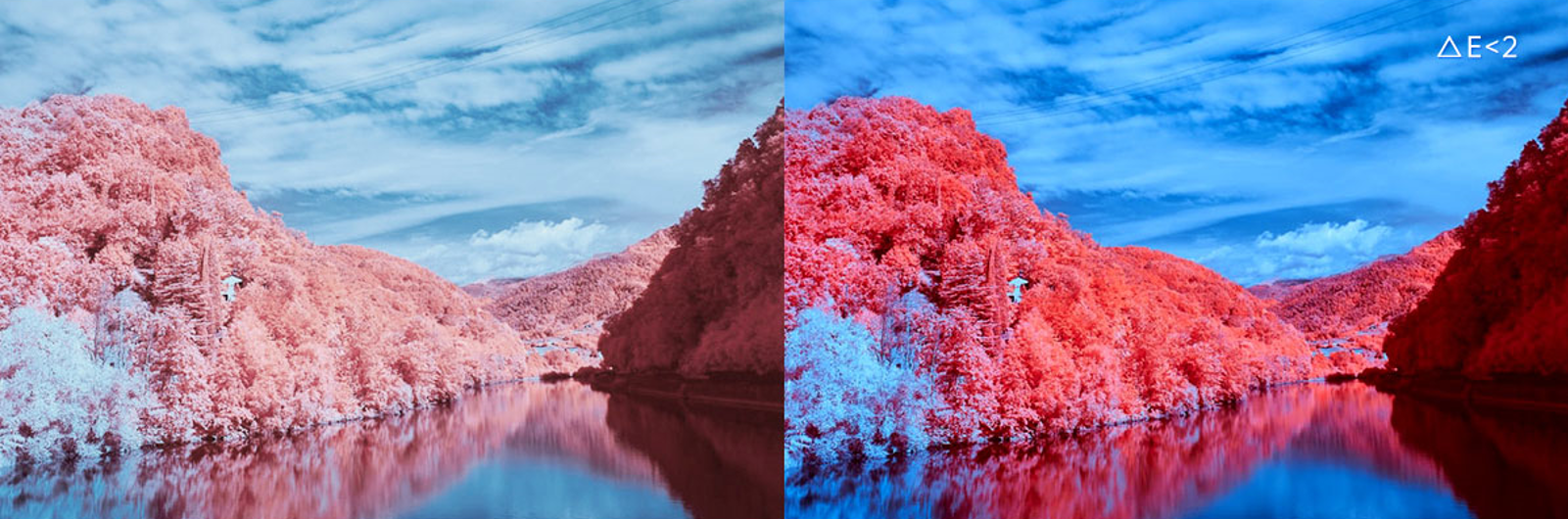
- Color Management
By using a colorimeter to examine and calibrate the original color gamut of the screen, and with the help of NovaStar's unique color management algorithm, the image booster will realign the LED screen's color gamut to approximate the standard color gamut of BT.709, BT.2020, DCI-P3, and eventually, the color gamut is adjusted to be consistent with the video source, eliminating color deviation and reproducing natural colors.
Before and after color management
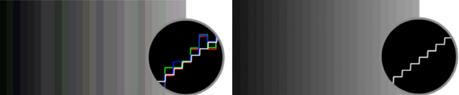
- Precise Grayscale
With the help of professional optical instruments, this feature individually corrects the 65,536 levels of grayscale of the driver IC to fix the display problems at low grayscale conditions, such as brightness spikes, brightness dips, color cast and mottling and achieve pinpoint accuracy in grayscale control, allowing for a significant improvement in the quality of LED display images.
Before and after precise grayscale adjustment
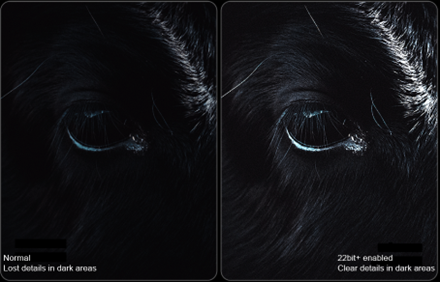
- 22bit+
Harnessing the power of image quality algorithms, the bit depth of low-grayscale on the screen is elevated, resulting in an incredible 64-fold surge in dynamic contrast. This process effectively addresses common issues such as grayscale loss and contour lines that arise in case of insufficient grayscale on the screen, allowing for richer grayscale shading and intricate detail presentation for on-screen images.
Before and after 22bit+ is enabled
Applicable Scenarios
The image booster is primarily designed to address the following issues:
- During the manufacturing process of LEDs, they are often not calibrated or subject to any color gamut restrictions. As a result, the color gamut displayed on the LED screen may not conform to any standard, leading to color deviations when compared to the video source. In such cases, the color gamut of the screen can be adjusted to match the video source, eliminating discrepancies and producing a more lifelike image.
- At low brightness or gray level, the grayscale of the screen is inaccurate and there may be display problems such as grayscale addition, grayscale spikes, mottling, and color cast.
- Display problems such as grayscale loss and contour lines may occur when the screen displays low-grayscale images.
Prerequisites
To use the image booster, please contact NovaStar technical engineers before the cabinets leave the factory. Color analyzer such as CA410-VP427, CA410-P427, and EYE2-400 will be used to perform color gamut and brightness calibration. The image booster parameters will be integrated into the cabinet library file (.ncp).
Procedure
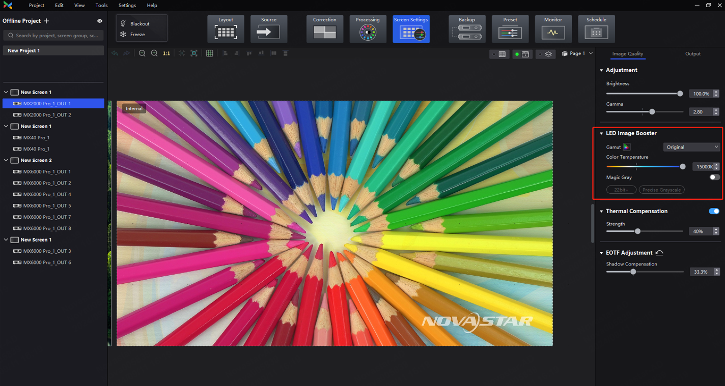
1. Select , and then find LED Image Booster on the right side of the screen under the Image Quality tab.
2. Manage color gamut.
Select an output color gamut from the drop-down list of Color Gamut. The output color gamut can be a standard color gamut, a custom color gamut, the original color gamut of the screen, or the color gamut of the input source (follow the input source).
To set a custom color gamut, click and select a color gamut in the attribute area of the color gamut screen. Then, adjust the parameters of red, green, blue, and white. You can also rename the custom color gamut.
3. Drag the slider to adjust color temperature.
4. Adjust the grayscale of the screen.
Toggle on Magic Gray to enable 22bit+ and Precise Grayscale
¶ HDR
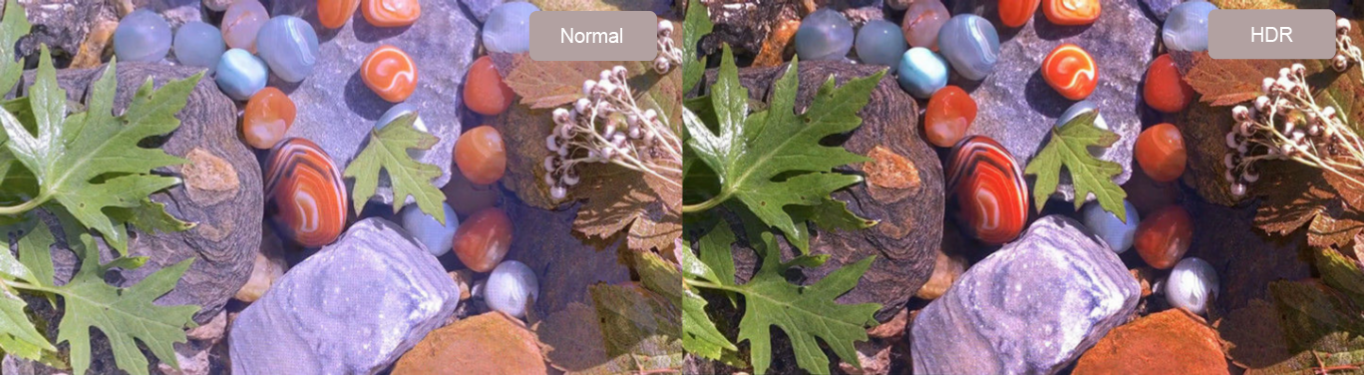
Overview
There are two HDR encoding formats supported: HDR10 and HLG. It complies with the SMPTE ST 2084/SMPTE ST 2086 standards, which allows for a wider color gamut, higher color depth, and greater brightness range. This makes the display quality richer, the contrast more vivid, and the details in shadow and highlight areas more refined.
Before and after HDR
Applicable Scenarios
- For on-site users requiring dynamic support for multiple encoding formats and real-time switching between SDR, HDR10 PQ, and HLG formats without disrupting video input, an automatic HDR format switching mode is available. They can also opt to manually select a specific format for output.
- For on-site users who require flexible input control, it supports automatically decoding HDR input source data and displaying each input attribute in detail. If there are missing or erroneous input source data, users can also choose to manually overwrite HDR attributes to correct the HDR input.
- For users who need a wider color gamut, they can select Rec.709, DCI-P3, and Rec.2020.
Prerequisites
Supports automatic parsing and manual setting of HDR. When the input source is 12G-SDI, DP 1.2, or non-standard HDR sources, manual setting of HDR attributes is also supported.
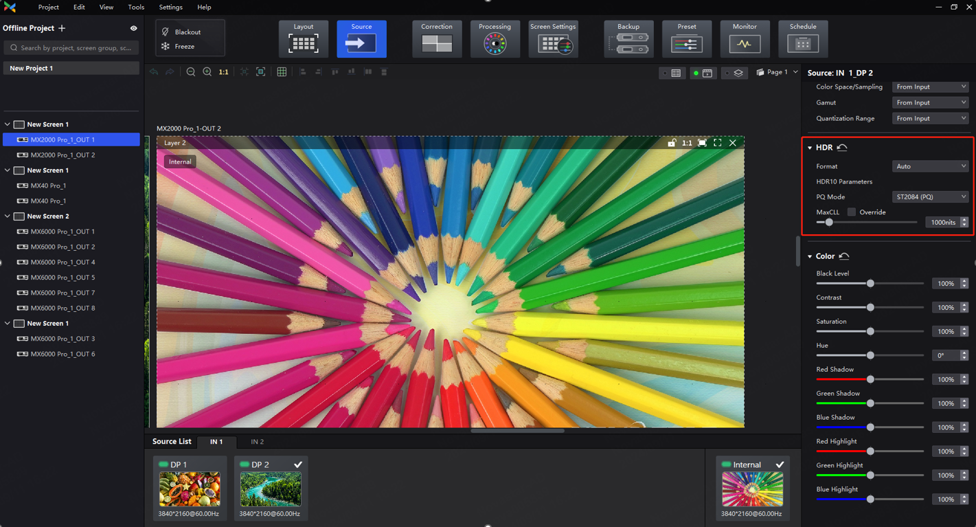
Procedure
- Select and then find HDR on the right side of the screen.
- Select an HDR format from the drop-down list of Format and set related parameters. Select Auto and the software will read the attribute value that comes with the input source.
When HDR10 is selected, the following parameters should be set:
- PQ Mode: The mapping method of video source brightness.
ST2084 (PQ): This mode 1:1 maps the brightness of the video source. The part of the video source that exceeds the screen's maximum brightness is adjusted to the maximum brightness.
ST2086 (Linear Mapping): This mode linearly maps the brightness of the video source according to the screen's maximum brightness to ensure that the ratio of the brightness of the source content remains unchanged.
- MaxCLL: Override the value for the maximum brightness of the video source, which only takes effect when Override is selected.
Notes
When using a 10-bit HDR source, the output load will decrease accordingly. See the following figure for details:
Single Ethernet port output load
|
Bit Depth |
COEX 1G MX40 Pro + A10s Pro MX6000 Pro/MX2000 Pro + A10s Pro |
COEX 5G CX40 Pro + CA50E MX6000 Pro/MX2000 Pro + CA50E |
|
8bit |
659,722 pixels |
2,951,200 pixels |
|
10bit |
494,792 pixels |
2,213,200 pixels |
¶ Thermal Compensation
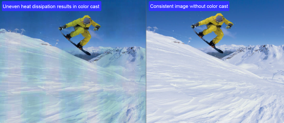
Overview
To address the redness at the edges of the cabinet/module and bluish-green color in the center caused by uneven heat dissipation of the screen, compensation coefficients must be dynamically adjusted based on the LED screen's status in real-time.
Before and after thermal compensation
Applicable Scenarios
Extended use of the LED screen can induce an increase in temperature, leading to varying degrees of attenuation in the RGB diodes. Usually, the Red diodes exhibit higher attenuation compared to G and B diodes in response to rising temperature, resulting in a bluish-green hue on the cabinet. Additionally, the overall display inconsistency could also be due to the uneven heat dissipation of the cabinet/module. This entails: 1) better heat dissipation at the edges; 2) chips generating more heat; 3) the power supply box areas being the hottest. Ultimately, these effects exhibit as reddish edges and bluish-green color blocks in the cabinet's center.
Prerequisites
To use Thermal Compensation, please contact NovaStar technical engineers before the cabinets leave the factory to collect thermal data of the cabinet and integrate the thermal compensation parameters into the cabinet library file (.ncp).
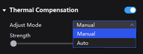
Procedure
- Select , and then find Thermal Compensation on the right side of the screen under the Image Quality tab.
- Set the Thermal Compensation switch to .
- You can adjust the thermal coefficients manually or automatically.
- Manual: Drag the slider to adjust the strength of applying the thermal coefficients.
- Automatic: The system automatically generates the application strength of thermal coefficients based on the screen status and does not support manual modification.
¶ 2.3 Frame Rate Processing
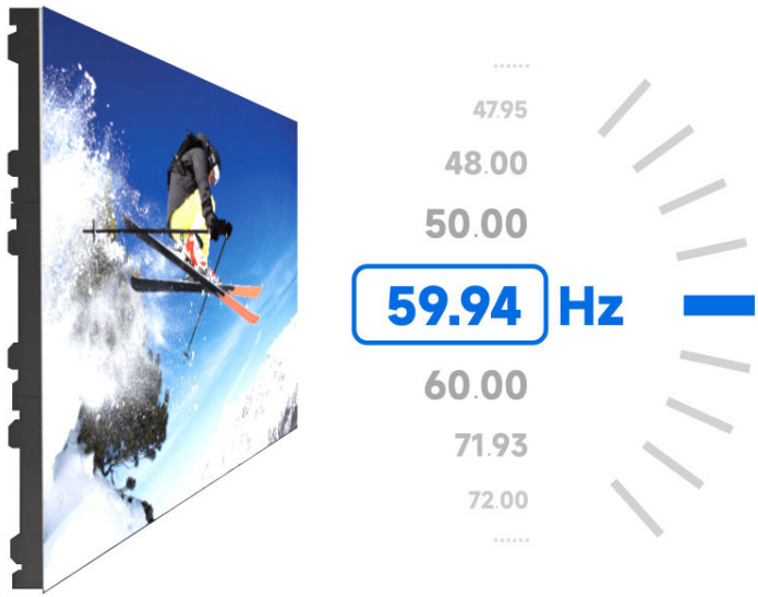
¶ Frame Rate Adaptive
Overview
To adjust the display effects for varying frame rates range from 23.98 Hz to the max frame rate supported by the screen (max frame rate is decided by the screen's hardware configuration), ensuring that the max brightness and color temperature remain consistent at different frame rates. It is suitable for scenarios that need to change the frame rate, such as using different types of video sources with different frame rates, and achieve perfect playback of high frame rate videos.
Frame Rate Adaptive
Applicable Scenarios
- For scenarios that require adjustments to frame rates, including upconverting or downconverting shooting, enabling or disabling frame multiplication, or using video sources with varying frame rates.
- To achieve flawless playback of high frame rate videos.
Prerequisites
- Currently, Frame Rate Adaptive is supported on the following driver ICs:
COEX 1G solution: ICND2055, ICND2065, ICND2069, MBI5253A, MBI5253B, MBI5754B, MBI5264, MBI5264B, MBI5264C, CFD555A.
COEX 5G solution: ICND2055, ICND2065, ICND2069, ICND2076, MBI5264, MBI5264B, MBI5264C.
More driver ICs will be supported in the future. If you have any questions, please contact NovaStar.
- To use Frame Rate Adaptive, please contact NovaStar technical engineers to integrate the frame rate adaptive parameters into the cabinet library file (.ncp).
Procedure
You can easily switch to different output frame rates via Screen Settings.
Notes
Flickering may occur when the selected frame rate exceeds the maximum supported by the screen.
For example, if the maximum frame rate is 196 Hz and a frame rate of 240 Hz is selected, flickering will occur since it exceeds the screen's hardware capability.
¶ Low Latency
Overview
Enabling Low Latency can reduce the delay in data processing and transmission of LED controllers by 1 frame. The latency of the whole system is illustrated in the following figure:
System Latency Components
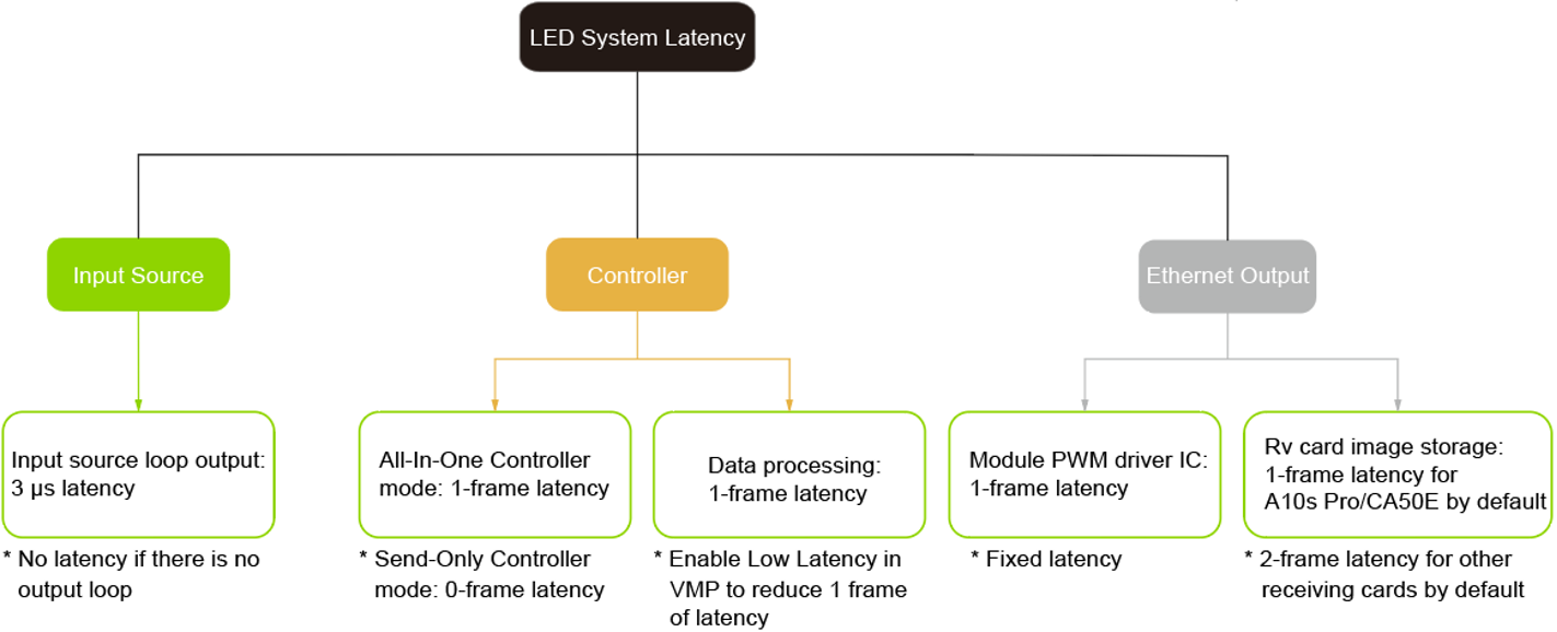
About System Latency
The latency of the whole system is cumulative, and no latency will occur without any relevant settings.
For example, using an A10s Pro receiving card, along with settings such as no loop output, Send-only Controller mode enabled, and Low Latency enabled in VMP, can result in a total system latency of two frames.
Applicable Scenarios
For scenarios where there is a latency between the input video source and the final display image on the LED screen.
Prerequisites
This feature is mutually exclusive with Genlock synchronization and frame multiplication.
NovaStar is actively working to resolve this issue in subsequent versions of VMP. For ongoing updates and more information, please visit the NovaStar official website at www.novastar.tech
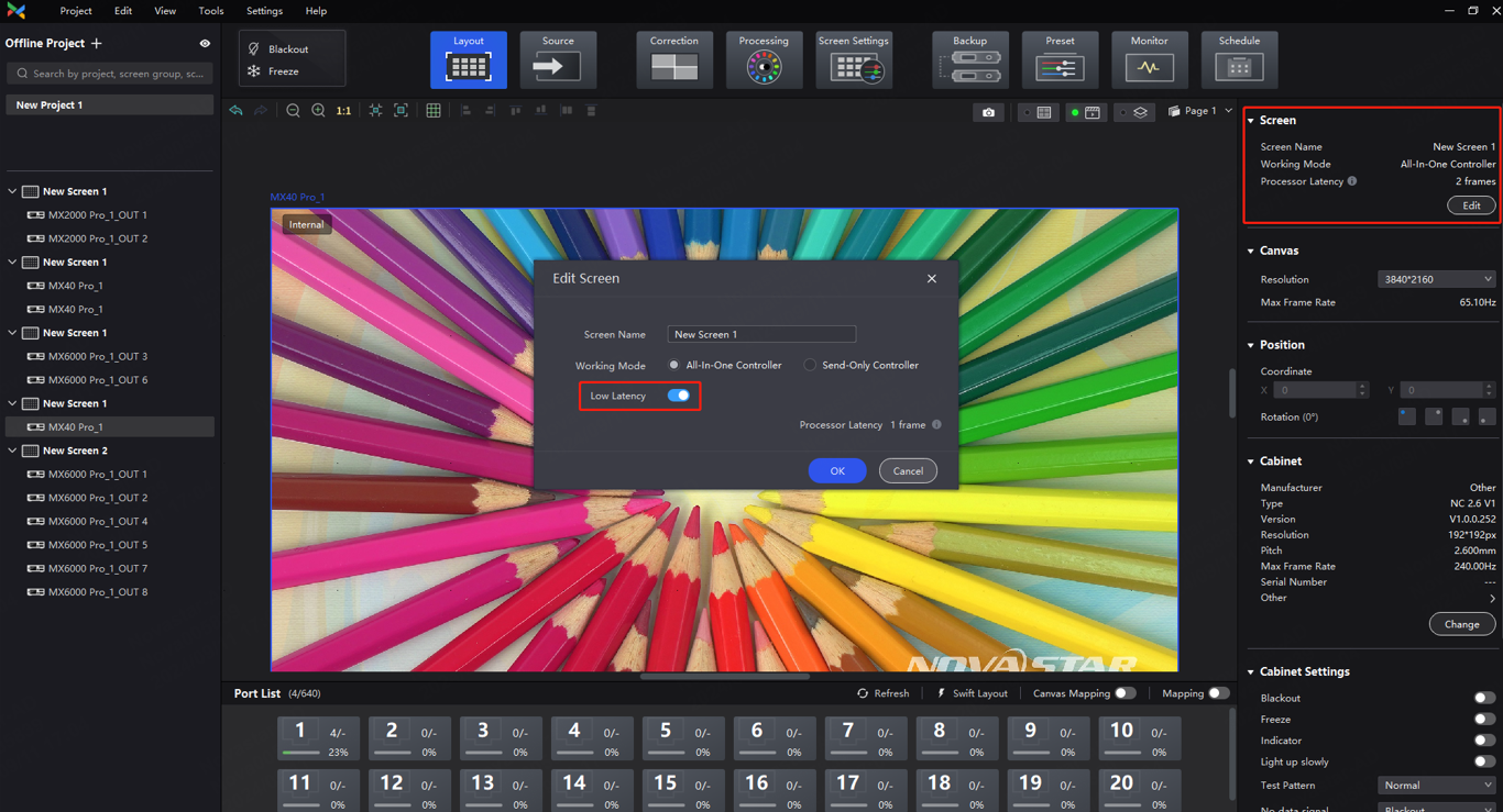
Procedure
- Select Layout, then find Screen on the right side of the interface and then click Edit.
- Set Low Latency on the pop-up window. When low latency is set to on, the latency at the data-sending end is reduced by 1 frame.
Notes
When Low Latency is enabled, please make sure all Ethernet ports load the cabinets vertically and share the same Y coordinate. If a custom configuration is required, such as a cabinet being loaded horizontally on Ethernet port 2 or starting at a different coordinate than port 1, enabling Low Latency may result in a decreased load.
¶ 2.4 Camera Shooting Optimization
¶ Genlock Synchronization
Overview
This feature enables the synchronization of various on-site systems, including the LED control system, shooting system, and rendering system. By combining these systems into a common signal synchronization system, it ensures that all system signals are precisely synchronized.
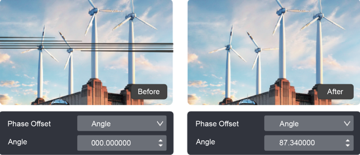
Additionally, this feature supports setting phase offsets and adjusting the phase of the video frame relative to the selected sync source displayed on the screen. This can help resolve issues such as black lines and scan lines.
Before and after phase offset
Applicable Scenarios
In a multi-system scenario, such as a shooting situation, black lines and scan lines may appear due to discrepancies between the camera's exposure time and the screen's refresh rate, or misaligned frequency and cycle. To remedy this issue, a Genlock generator can be utilized to synchronize the LED controller and camera, while also adjusting the output phase offset. By doing so, the system can maintain precise synchronization between the LED screen and camera.
Prerequisites
1. Make sure that the controller and camera both use the same Genlock signal generator. Additionally, the camera used should meet the following requirements:
- It is equipped with a Genlock input interface capable of supporting the synchronous signals of multiple frame rates.
- It includes a Genlock signal phase offset function (multi-camera shooting may require this function).
- The LED display fills out the camera's shooting area. (To fill out the display, modify the distance or use a long-focus lens.)
- No moiré pattern on the screen during shooting (moiré pattern can be prevented by making cameras slightly out of focus).
- Observe the image in the viewfinder or monitor and adjust the ISO to avoid overexposure.
2. Mutually exclusive function: Low Latency.
Procedure
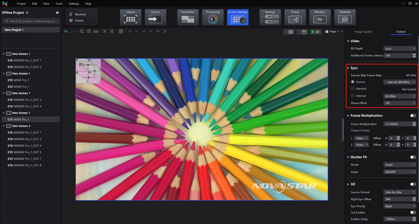
1. Select Screen Setting, and then find Sync on the right side of the screen under the Output tab.
2. Select a sync signal for the display frame rate.
- Active Source: Sync with the frame rate of the active source.
- Genlock: Sync with the frame rate of the Genlock signal. When the shutter fit function of the controller is enabled, kindly ensure that this option is selected. In addition, the controller and the camera need to use the same Genlock signal generator.
- Internal: Sync with the frame rate of the controller's internal clock.
3. Set the phase offset to adjust the start phase of the output frame rate of the sync source. This will ensure that the display start time of the LED screen is in sync with the exposure start time of the camera, effectively eliminating issues such as black lines and image tearing when using a camera to capture LED screens.
- Angle: Specify the required phase offset as an angle relative to a circle. (For example, for a 60 Hz sync source, 180° corresponds to 1/120s.)
- Fraction: Specify the required phase offset as a fraction of the sync source cycle. (For example, for a 60 Hz sync source, 50% corresponds to 1/120s.)
- Absolute: Set the required phase offset directly in frames, and the output source will be delayed according to the absolute value.
4. To examine whether Genlock synchronization is successfully enabled, you can use any of the following methods:
- If you notice multiple dark or bright lines on the LED screen through the camera, keep all systems remain still and observe the black or white lines in the camera monitor or viewfinder for at least one minute. If these lines move, it indicates the Genlock synchronization is not working and you may want to double check cables, frame rates, and other relevant factors. If there is no movement, you may continue with the operation.
- Change the frame rate of the Genlock generator, unplug the Genlock generator, or switch to another sync signal source (such as internal). Next, observe the camera monitor for movement of the black lines. If they move, it indicates the Genlock synchronization is working.
Notes
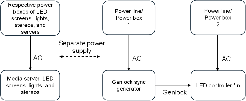
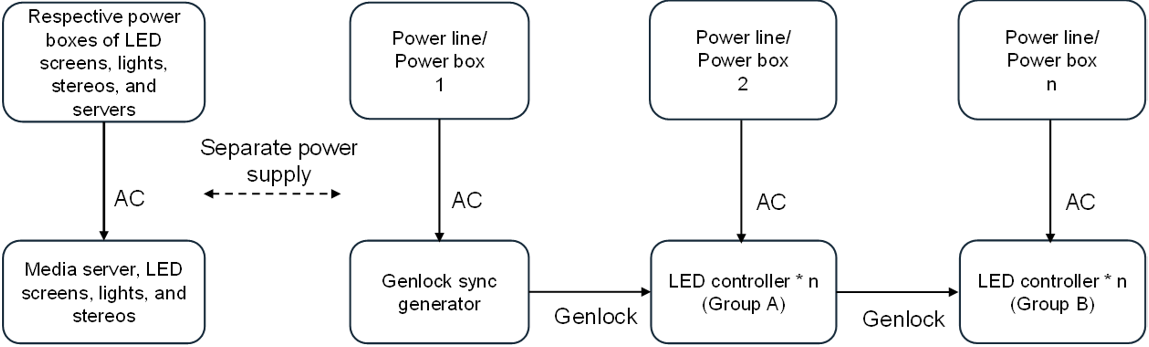
1. It is recommended to separate the Genlock signal generator and other high-power devices (such as media servers) for power supply. When the on-site power supply network is optimal, it can share the same power line with the LED controller.
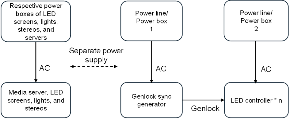
2. For complex sites, one or more separate LED controllers are required to be powered separately from other high-power devices (such as LED screens, lights, and stereos). It is not recommended to use the same industrial power supply box for LED controllers and other high-power devices (this includes LED controllers and other devices sharing the same power supply box but using different power supply ports).
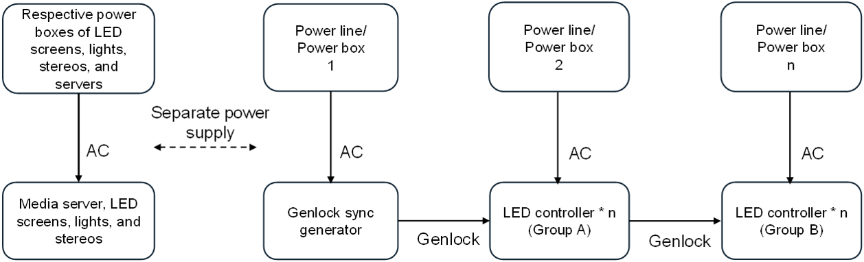
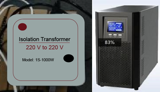
3. When the stability of the on-site power supply is not guaranteed, it is recommended to add an isolation transformer or UPS before the Genlock signal generator and LED controllers. It is imperative that the capacity of the isolated power supply must meet the requirements of the sync generator and LED controller.
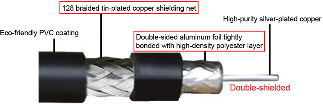
4. Double-shielded cables should be used for the Genlock connection.
¶ Shutter Fit
Overview
This feature adapts the screen and camera shutter to produce better filming results. It supports custom adjustment from 22.5° to 360° with an accuracy of up to 0.001°. Commonly used angles include 180°, 270°, and 360°.
Before and after Shutter Fit
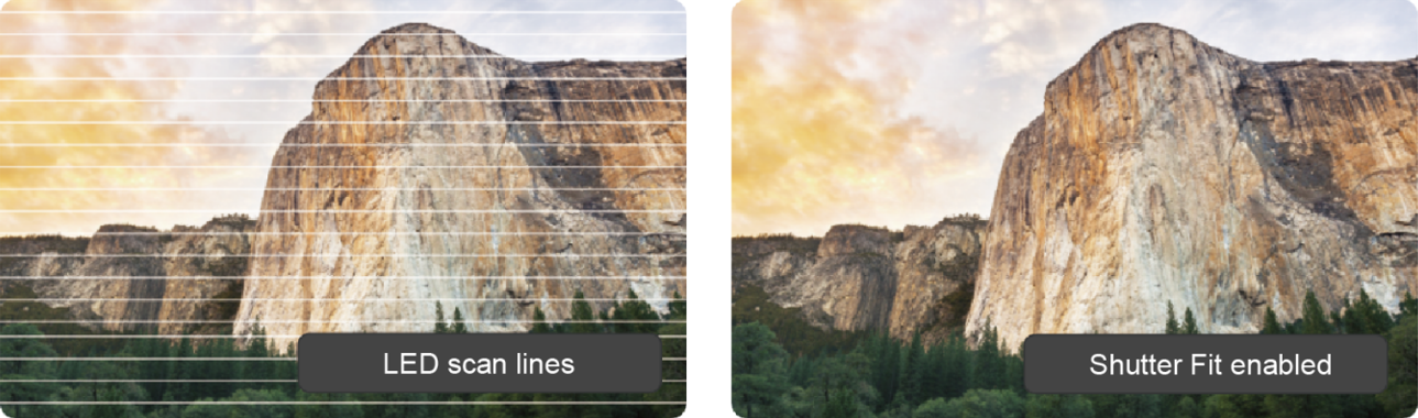
Applicable Scenarios
During the debugging, Shutter Fit can be used to synchronize the camera's shutter speed and automatically adjust the screen according to the camera's exposure time and frequency. By combining this feature with phase offset, scan lines during shooting can be effectively eliminated.
Prerequisites
1. Ensure that the controller and camera Genlock are successfully synchronized. (For the detailed procedures, see 2.4.1 Genlock Synchronization)
2. Shutter Fit needs to work with Frame Rate Adaptive. Please contact NovaStar technical engineers to integrate the frame rate adaptive parameters into the cabinet library file (.ncp) before the cabinets leave the factory.
3. The camera must meet the following requirements:
- It must have a real-time monitoring function, which allows you to view the picture recorded by the camera immediately. This can be done through digital viewfinders, LCD monitors, or external monitors.
- It must have a focus fine-tuning function.
- The shutter time/speed must be adjustable.
Procedure
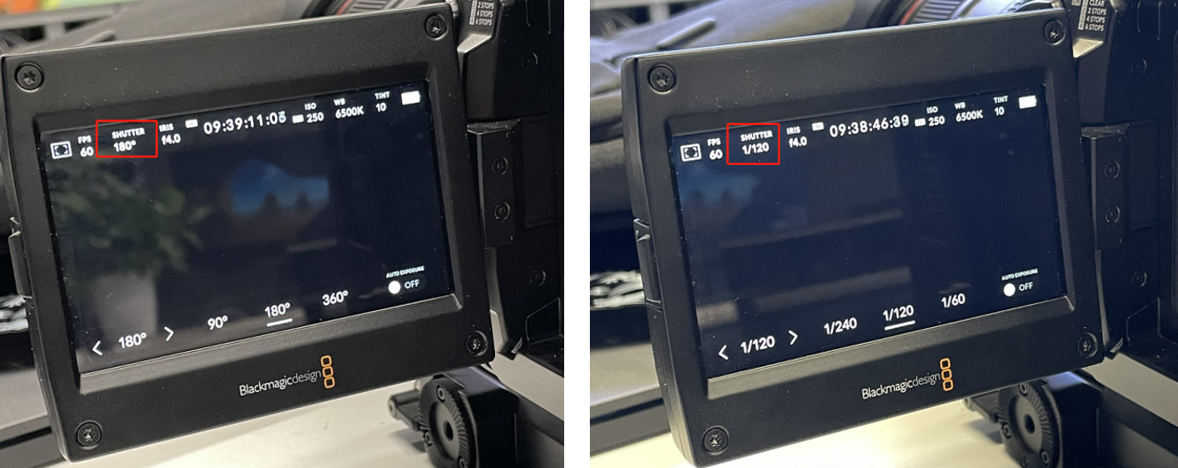
1. Check the current shutter angle/speed in the camera settings menu.
For most rolling shutter cameras, the total exposure time Ttotal = Tset +△T.
Camera shutter angle/speed example (the position of parameters may vary among different camera models, for reference only)
2. Open VMP, select Screen Settings, and then find Shutter Fit on the right side of the screen under the Output tab.
3. Set the toggle switch to on, select a mode and then set the related parameters.
- Angle: Choose the camera shutter angle, typically 180°, 270°, 360°.
- Speed: Enter the camera shutter speed (1/x s), and the system will automatically calculate the exposure time.

Notes
After adjusting the frame multiplication/shutter fit, the original phase offset will no longer apply and needs to be readjusted.
¶ Adjust Mode
Overview
Storing multiple sets of display configurations for a given screen type allows you to select different mode parameters based on the application scenario. This ensures that LED screens are able to achieve optimal display quality in various scenarios.
Applicable Scenarios
In the rental business, the same cabinet can be used for multiple purposes by adjusting mode parameters according to the required display effect based on the scene set-up.
For example, a P3.91 cabinet can be used in high-brightness mode for outdoor usage and switched to low-brightness mode to eliminate scan lines for xR virtual shooting.
Prerequisites
To use different modes, please contact NovaStar technical engineers to configure mode parameters into the cabinet library file (.ncp) according to the application scenarios before the cabinets leave the factory.
Procedure
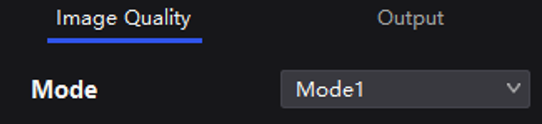
- Select Screen Settings, and then find Mode on the right side of the screen under the Image Quality tab.
- Select a mode based on the application scenario to achieve optimal display effects for the LED screen.
¶ Frame Multiplication
Overview
- Frequency Multiplication
By doubling or reducing the frame rate, the frame rate synchronization between multiple processors can be matched, supporting frame rates of up to 240 Hz (depending on the maximum frame rate of the screen). This can effectively resolve synchronization issues between multiple processors. When combined with a high frame rate, it can deliver optimal image quality for both camera lenses and the human eye.
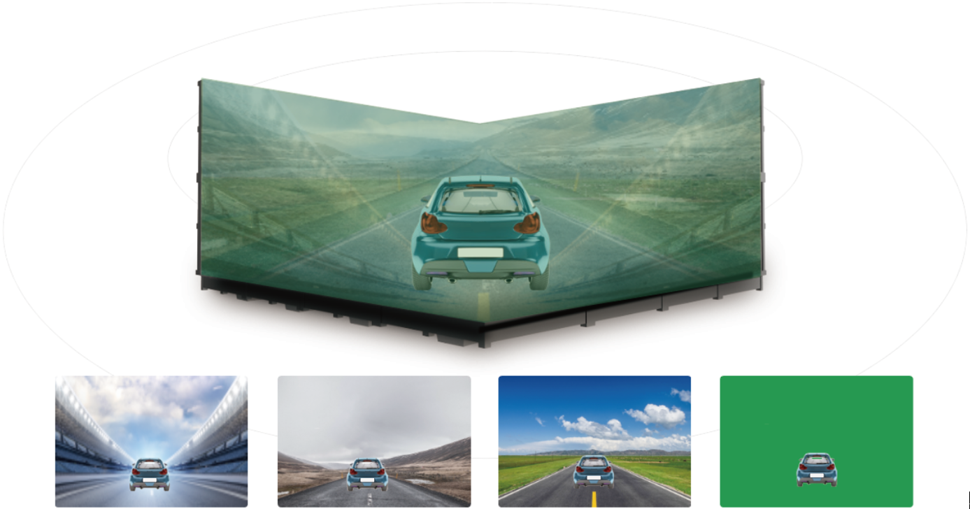
- Frame Interpolation
Through frame interpolation, users can fuse scenes in video output using various sources such as images captured from different angles, independent video sources, or solid color images. By synchronizing the camera and setting an appropriate phase offset, it's possible to capture normal video frames alongside inserted image frames to achieve multi-camera shooting.
Applicable Scenarios
- The input frame rate does not match the frame rate of other systems, or the video source needs to be played at high frame rate.
- To output images captured from multiple camera angles with different backgrounds on the same timeline. Or insert a solid green background to allow for easy post-production adjustments.
Example of Frame Multiplication
Prerequisites
Mutually exclusive function: Low Latency.
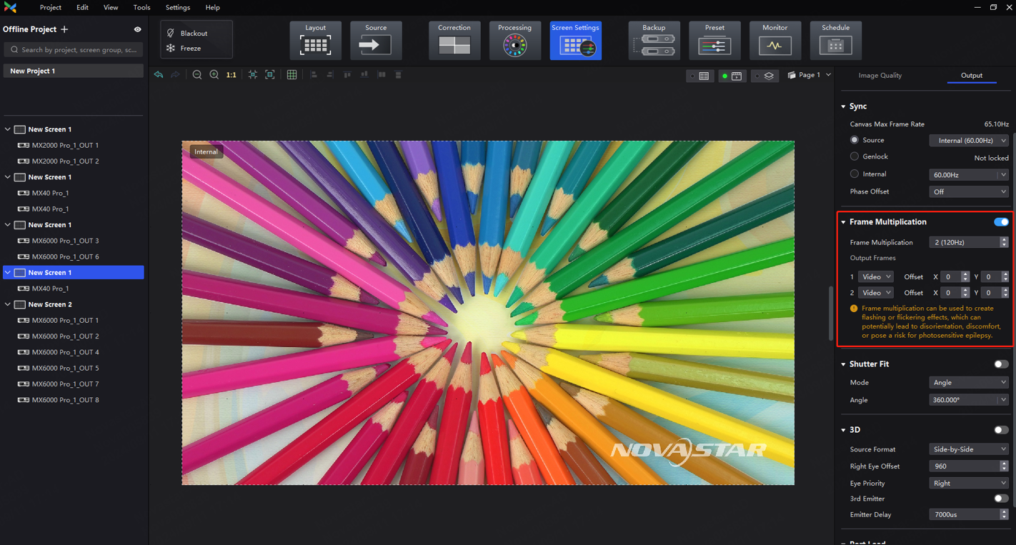
Procedure
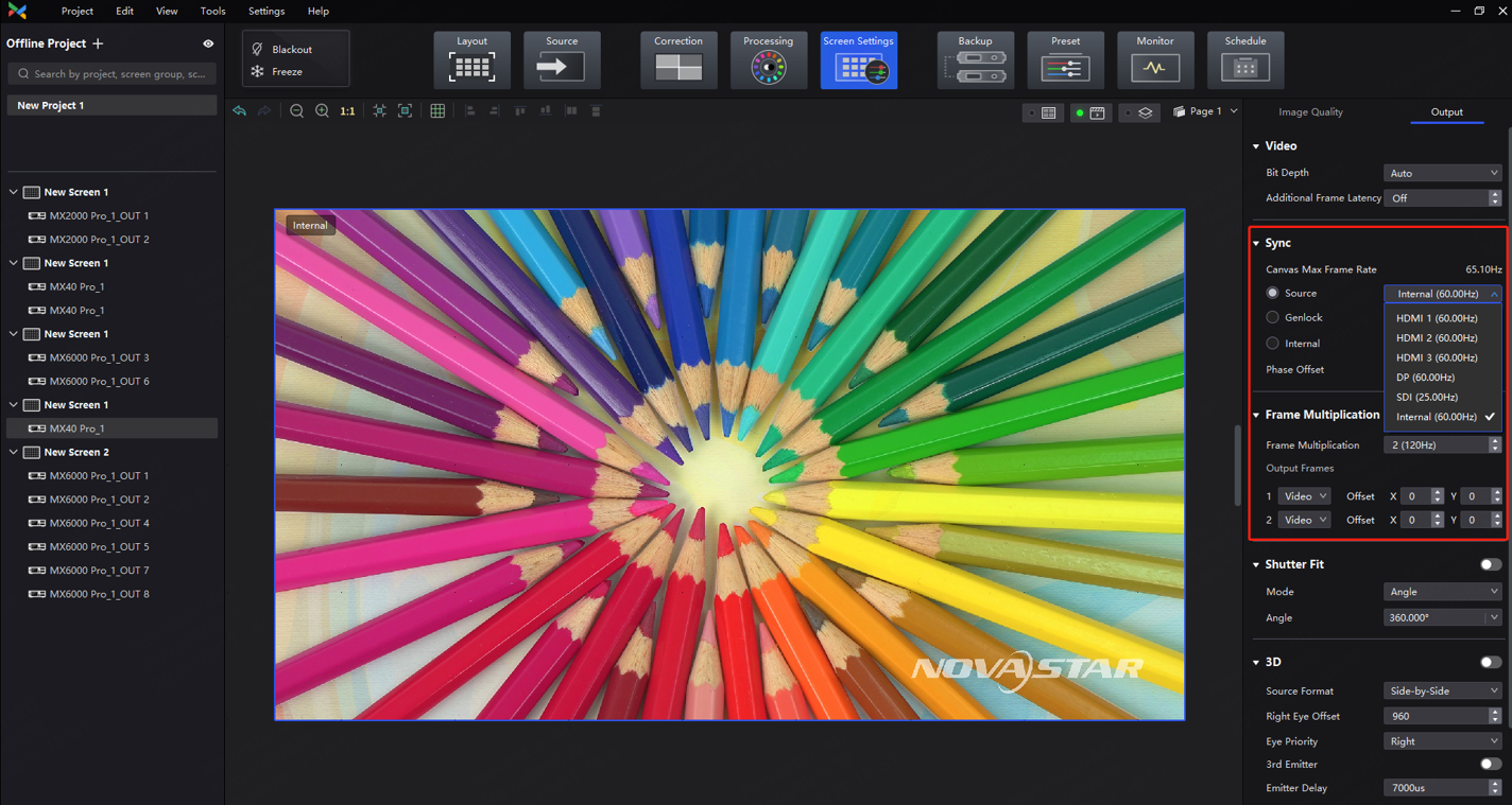
- Select Screen Settings, and then find Frame Multiplication on the right side of the screen under the Output tab.
- Set the frame multiplication and display method for each frame, as demonstrated in the example settings provided below.
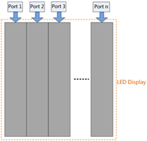
- Frame Multiplication: The current frame rate (60 Hz) is multiplied by 4 to 240 Hz, with 4 frames displayed within 1/60 second.
- Video: The first, second, and fourth frames display the input source image. The first frame displays the image from the coordinates (0, 0), the second frame displays the image from the coordinates (128, 0), and the fourth frame displays the image from the coordinates (-1920,-16384),
- Color: The third frame displays a solid green image.
Notes
When Frame Multiplication is enabled, the output load of the device will decrease accordingly. See the following figure for details:
Single Ethernet port output load
|
Frame Rate |
COEX 1G MX40 Pro + A10s Pro MX6000 Pro/MX2000 Pro + A10s Pro |
COEX 5G CX40 Pro + CA50E MX6000 Pro/MX2000 Pro + CA50E |
|
60 Hz |
659,722 |
2,915,200 |
|
120 Hz |
329,861 |
1,475,600 |
|
144 Hz |
274,884 |
1,229,600 |
|
240 Hz |
164,931 |
737,800 |
When setting frame multiplication, ensure that the frame rate and load range are appropriate to avoid system overload, which may lead to screen flickering.
¶ 2.5 Color Management
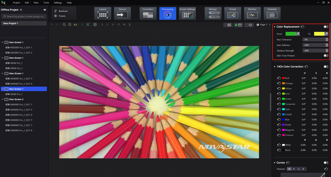
¶ Color Replacement
Overview
This feature is for replacing one color in the image with another color without affecting other colors.
Before and after Color Replacement
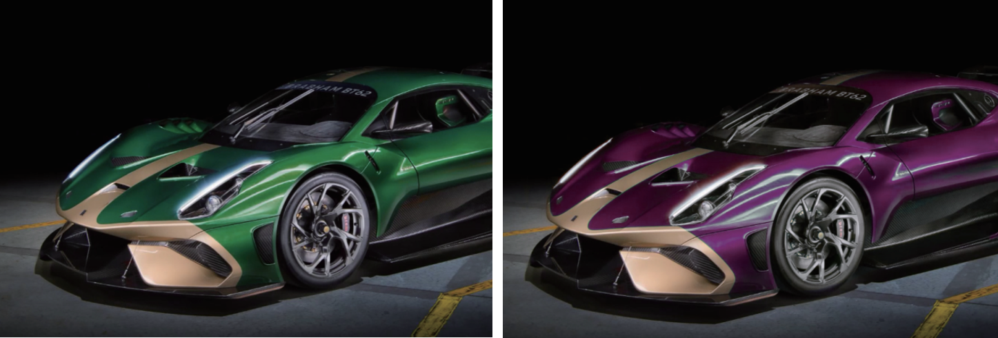
Applicable Scenarios
Typically, advertising videos feature products in only one color. However, promoting products in other colors from the same series requires laborious and time-consuming re-rendering. To simplify this process, the color replacement function enables users to directly replace the specified color in their advertising video with the desired color.
Procedure
1. Select Processing and then find Color Replacement on the right side of the screen.
2. Set the Color Replacement to on and then set the colors before and after replacement.
- Method 1: Click the color area to open the color palette and set a color.
- Method 2: Click the eyedropper and select a color in the topology area.
3. Set Hue Tolerance, Hue Softness, Shadow Strength, and Skin Tone Protect.
- Hue Tolerance: Indicates the hue range of the color to be replaced. The greater the value, the larger the replacement area.
- Hue Softness: Indicates the hue softness of the transition area. The greater the value, the larger the range of the hue transition area, and the smoother the transition.
- Shadow Strength: Indicates the gradient of the highlight or shadow area. The greater the value, the weaker the layering effect in low-saturation areas.
- Skin Tone Protect: Keeps the skin tone as original as possible. Only applicable to samples that include skin color areas.
Notes
- For best results, choose samples that have a significant color contrast between the foreground and background.
- When selecting the color to be replaced, it is recommended to choose the original color with higher saturation for replacement. Selecting pixels with very low saturation may cause issues such as excessive color intensity, texture loss, and incorrect replacement effect.
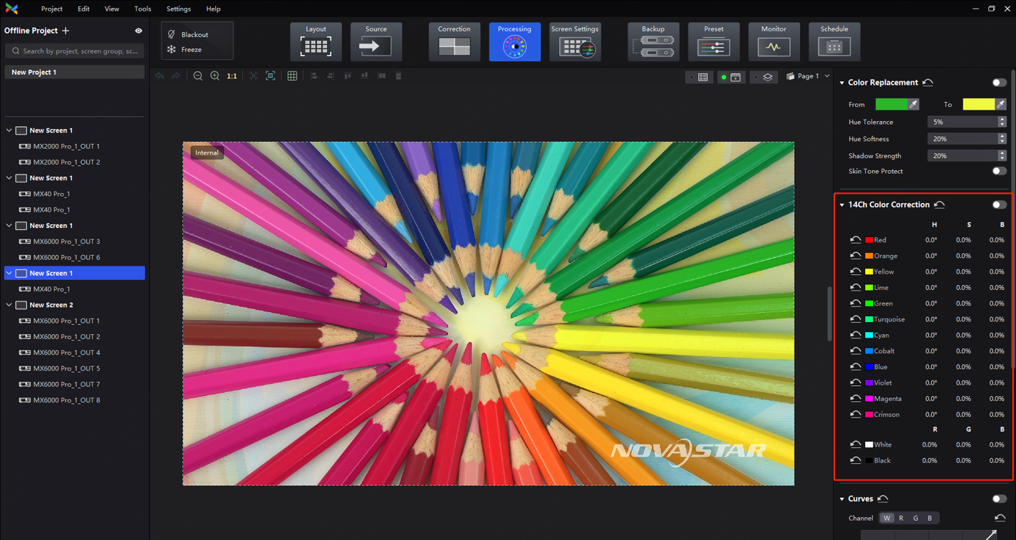
¶ 14Ch Color Correction
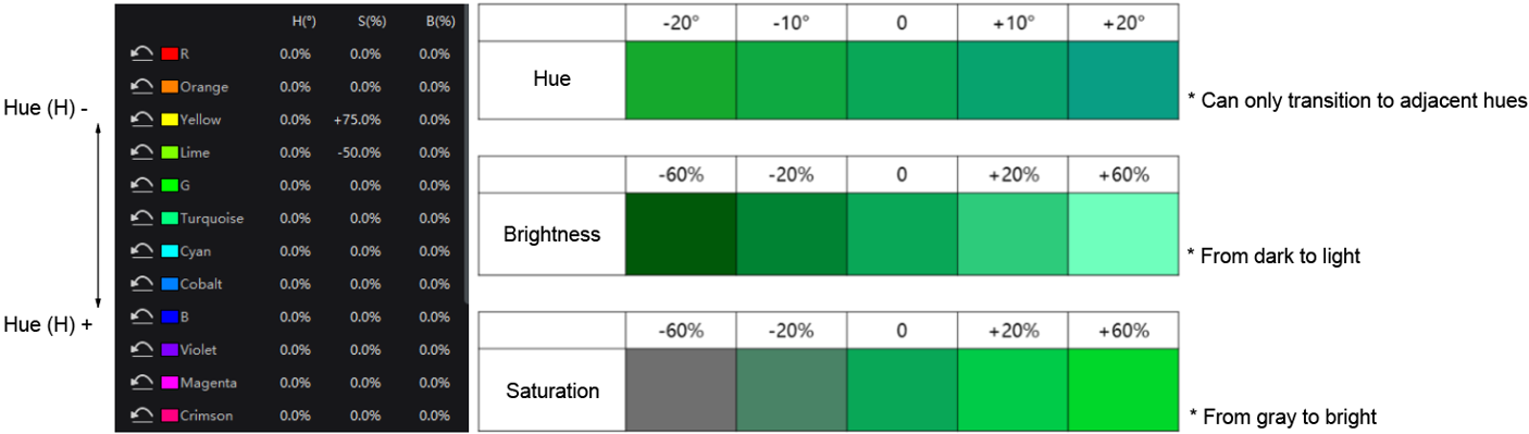
Overview
The feature color correction of 14 colors: red, orange, yellow, lime, green, turquoise, cyan, cobalt, blue, purple, black, white. It corrects the active colors on the screen to make them more consistent with the target color.
For the 12 colors, it adjusts hue, saturation, and brightness. For black and white, it adjusts R, G, and B.
Applicable Scenarios
When precise on-site color display is required, such as when displaying green color, it is essential for color coordinates to meet certain standards. If the color captured by the camera does not accurately match the color displayed on the screen, users can compare the colors with their naked eyes, and then adjust the hue, saturation, and brightness to make them closer to the target color.
14Ch Color Correction (using green as an example)
Procedure
- Select Processing and then find 14Ch Color Correction on the right side of the screen.
- Set the 14Ch Color Correction to on. Click a value of a color to edit it, for example.
|
Parameter |
Change in Value |
|
Hue (H) |
Positive value: The hue angle changes counterclockwise. |
| Negative value: The hue angle changes clockwise. | |
|
Saturation (S) |
Decrease to -100%: The 12 colors are gradually diluted. |
| Increase to +100%: The 12 colors are more vivid and rich. | |
|
Brightness (B) |
Decrease to -100%: The 12 colors gradually darken. |
| Increase to +100%: The 12 colors are brighter, and the colors seems to be diluted. |
Notes
- When adjusting colors for floor tile screens and sky screens, please adjust the hue first, and then adjust the brightness and saturation to achieve overall color consistency between the floor tile screens, sky screens, and upright screens.
- For the 12 colors, negative value means transitioning to the previous hue and positive value means transitioning to the next hue.
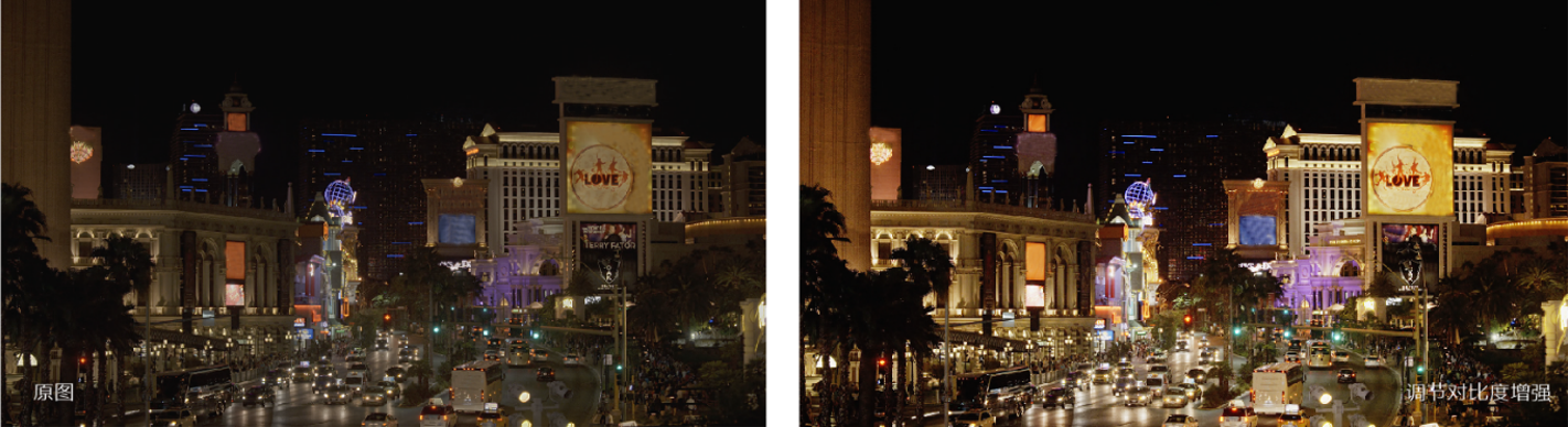
¶ Color Curves
Overview
This feature can be used to quickly adjust the brightness and hue of the image, and customize the color presentation under different gray levels.
Before and after contrast enhancement
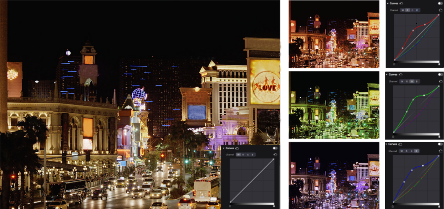
Comparison of color rendering effects after adjustment
Applicable Scenarios
Customize the response curves for red, green, blue, and white to enable independent fine-tuning of highlights and low grays. This ensures that the screen does not get overexposed from high brightness while preserving rich details in low grays. Additionally, this feature allows for fine-tuning of the screen display to compensate for differences in ambient light and camera performance.
Procedure
1. Select Processing and then find Curves on the right side of the screen.
2. Set the Curves to on.
The color curves can adjust the brightness of all gray-scale images, including low grays, mid-tones, and highlights.
- If the low gray part of the image is dark, raising the left half of the curve can brighten the low gray area.
- If the highlight part of the image is too bright, lowering the right half of the curve can reduce the brightness of the highlights.
- Adjusting both low grays and highlights can adjust the contrast of the image.
- Adjusting color channels separately can change the hue of the image.
3. Drag the slider at the bottom of the curve diagram to set the curve adjustment range. Click anywhere on the curve to add an adjustment point and drag the point to adjust the curve. The Input and Output values indicate the absolute coordinates of the adjustment point in the diagram.
4. Click on the right of Channel to reset the color curve of the current channel. Click next to Curves to reset all color curves.

Notes
- The adjustment pattern of the color curves is consistent with that of Photoshop, but differs from DaVinci.
- Up to 17 adjustment points are supported on one curve.
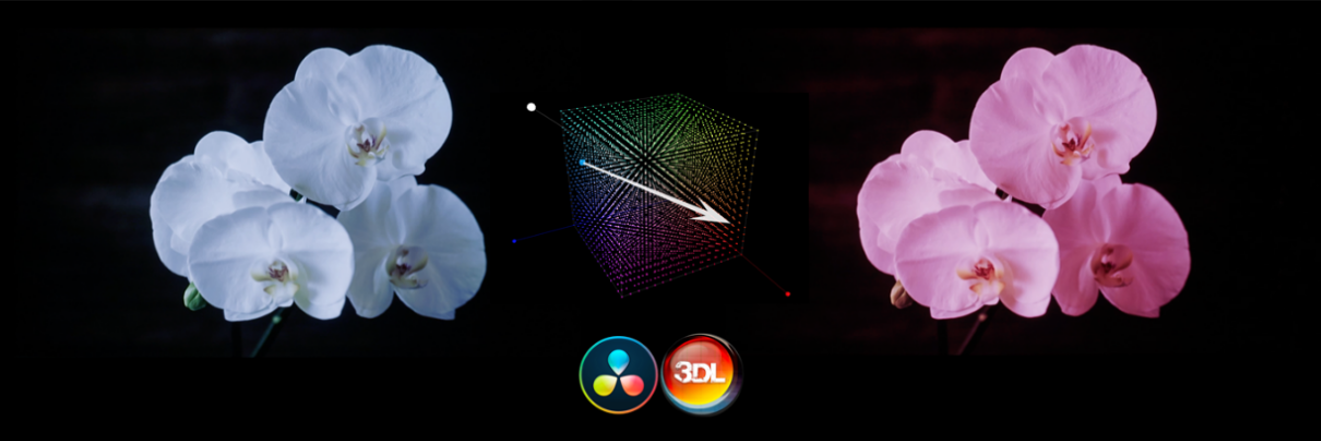
¶ 3D LUT
Overview
A set of mapping relationships are defined in the 3D LUT file (.cube) to adjust the colors of the video source. It is commonly used in the film and image processing industries. With this feature, you can change target colors without affecting neutral gray and other colors, which eliminates the issue of layer merging and maintains smooth color transitions. Additionally, this feature provides precise control over the entire color space, offering more accurate colors and enhancing the overall effect.
Before and after loading 3D LUT file
Applicable Scenarios
- When using a LED screen as the background for xR virtual shooting, failure to perform color correction can significantly deviate from real-world colors, leading to distortion of the shooting background.
- To achieve a specific display style, the video source may require creative color modifications. For example, the same set of video sources can be converted into different styles, such as vintage, black and white, or bright.
Prerequisites
To use this feature, please prepare a 3D LUT file (.cube) with a precision of 17×17×17. This file can be generated from professional color correction software such as DaVinci, Photoshop, 3D LUT Creator, among others.
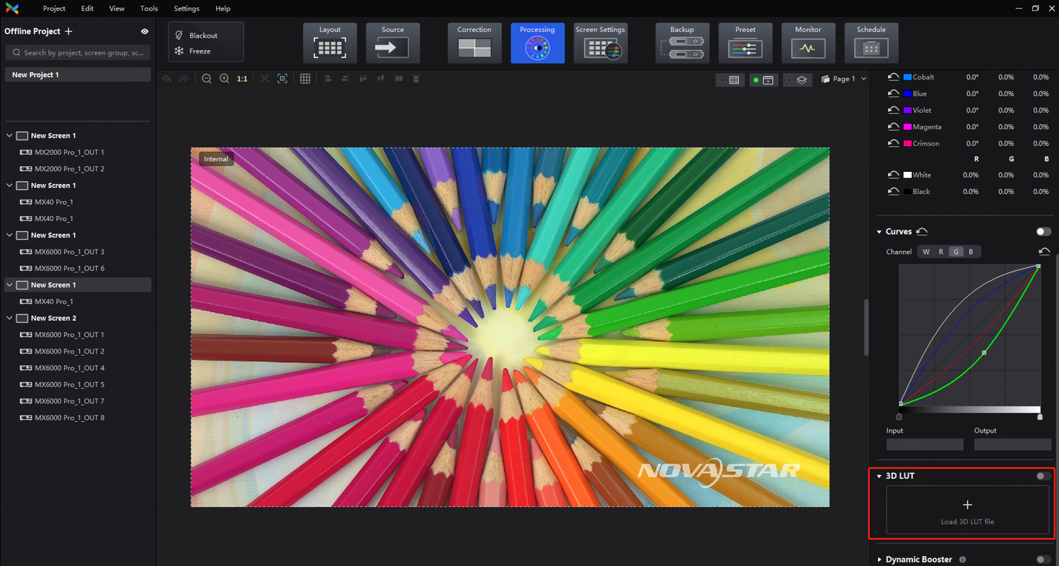
Procedure
- Select Processing and then find 3D LUT on the right side of the screen.
- Click anywhere in the Load 3D LUT File area, select a file and open it.
- Set the 3D LUT to on and drag the slider to adjust the strength of the 3D LUT.
- When the slider is set to 0%, the original image is displayed.
- When the slider is set to 100%, the image processed by 3D LUT is displayed.
- When 0% < Strength < 100%, the final display effect is somewhere between the original image and the image processed by 3D LUT.
¶ 3. COEX Series Introduction
¶ 3.1 COEX VMP
VMP (Vision Management Platform) is designed with a concept of opening platform, offering a seamless, all-around user experience for device management, input source configuration, screen configuration, screen correction, color processing, screen adjustment, screen monitoring, preset management, and screen maintenance. Its WYSIWYG interface provides a highly convenient and responsive experience for users. Currently, VMP is compatible with both Windows and Mac operating systems.
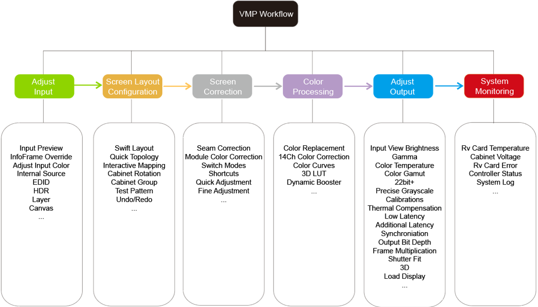
¶ Workflow
VMP Workflow
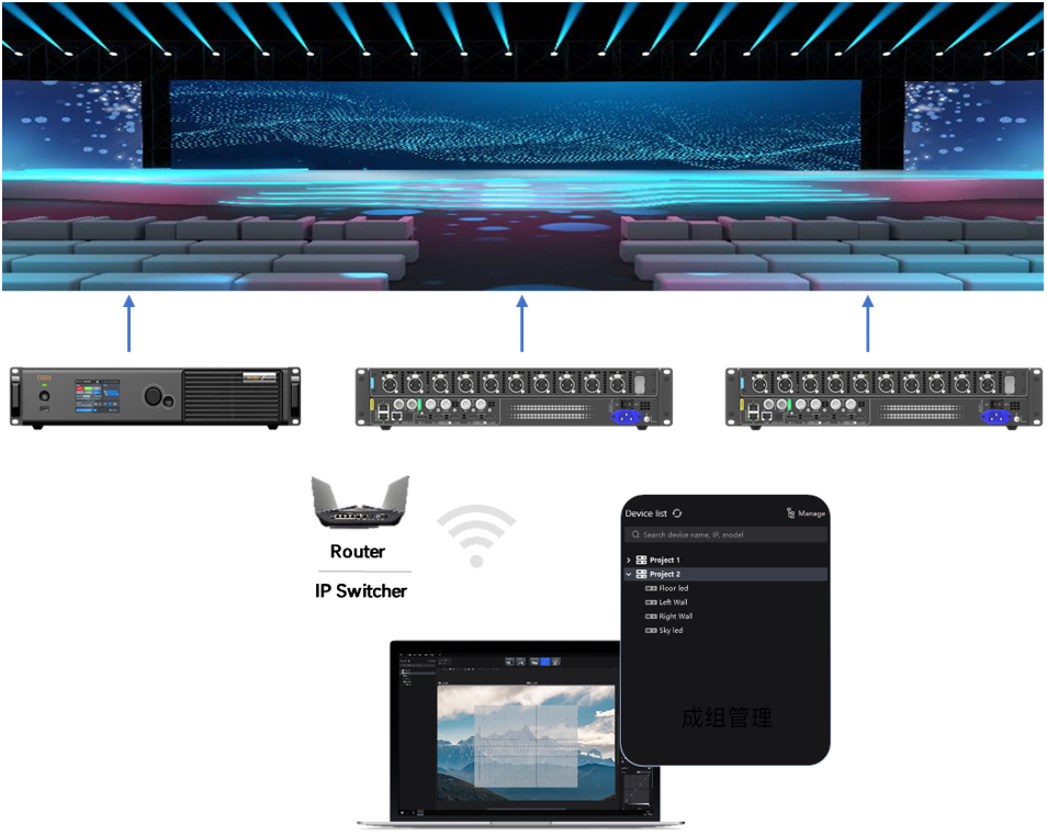
¶ Group Management for Easy Control
Managing devices by dividing screens into groups. Hosting large-scale live events with multiple screens has never been this easy.
Managing devices by groups
¶ No Rectangle Restriction, Free Screen Layout
Irregular screens don't need to follow rectangle restrictions. When calculating screen resolutions, blank pixels aren't counted toward the total capacity for more efficient use of the Ethernet port's load capacity.
No rectangle restriction
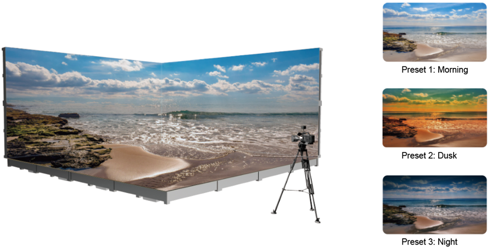
¶ One-Click to Apply Presets
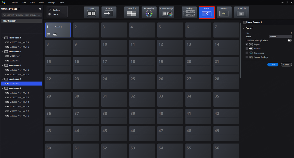
For quick configuration in various scenarios, adjust display parameters such as brightness, color temperature, and gamma ahead of time and save them as presets. You can save up to 50 customizable presets which can be easily applied or switched with just one click during shooting.
Switching Presets
Click Preset on the main interface of VMP to set up presets.
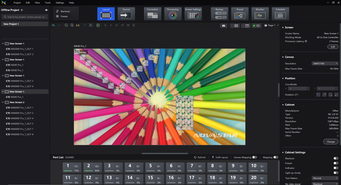
¶ Pre-configure in Offline Mode
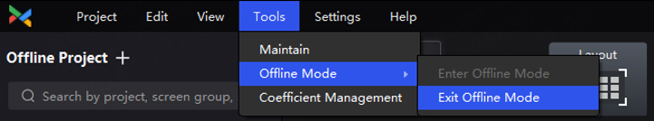
Before the LED screen is constructed on-site, you can add offline devices and pre-configure the screen settings. You can then easily import the pre-configured settings for swift and hassle-free usage of the LED screen.
Select Tools > Offline Mode from the VMP toolbar to enter or exit offline mode.
¶ NCP File, One-stop Management
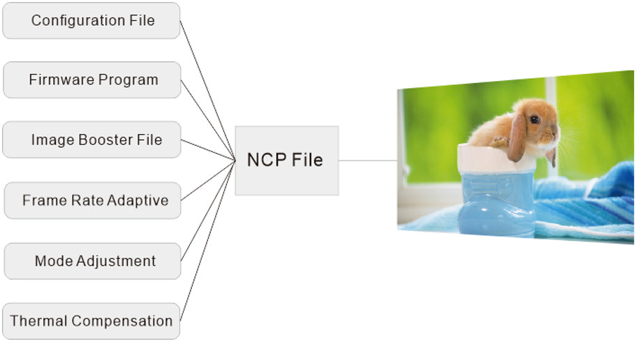
Six in one, the NCP file combines the cabinet configuration file, receiving card firmware program, image booster (cabinet optical correction), frame rate adaptive parameters, mode adjustment parameters, and thermal compensation (cabinet thermal correction) into one file. By uploading the NCP file from a computer or pre-load the file in the control system, users can utilize the NCP file at any time to light up the screen with a few clicks and achieve optimal display effects.
To generate the NCP file, please contact NovaStar technical engineers before the screen leaves the factory.
NCP File
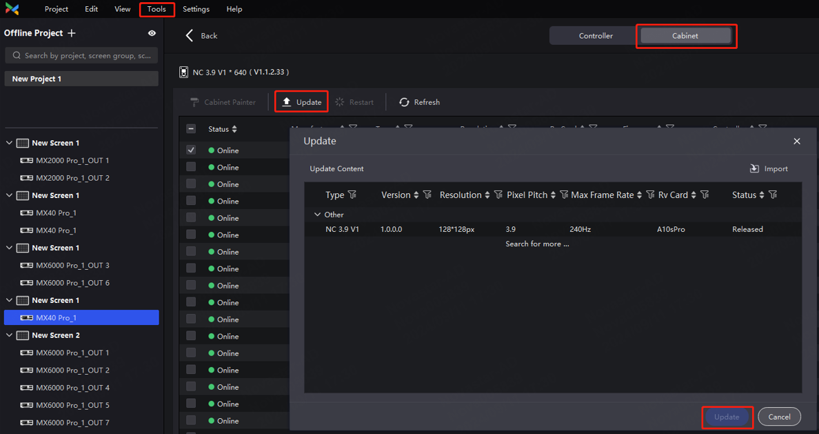
After receiving the NCP file, select Tools > Maintain from the VMP toolbar. Under the Cabinet tab, you can choose the cabinet that needs to be updated, then click on the Update button to upload the NCP file. You can also select Settings > Cabinet Library to manage NCP files.
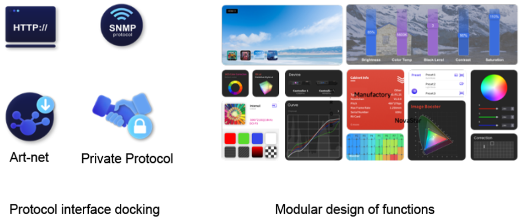
¶ Open Protocol and Secondary Development
- The protocol interface is well-designed and user-friendly.
The open protocol documents can be obtained from NovaStar website at www.novastar.tech.
- Flexible configuration and free combination of functional components are possible due to the protocol's support for modular design.
¶ 3.2 COEX Single-Card Controller Specifications
|
Feature |
MX40 Pro (1G) |
MX30 (1G) |
MX20 (1G) |
KU20 (1G) |
CX40 Pro (5G) |
|
Load Capacity |
9,000,000 pixels |
6,500,000 pixels |
3,900,000 pixels |
3,900,000 pixels |
9,000,000 pixels |
|
Inputs |
3x HDMI 2.0 (IN + LOOP) 1x DP1.2 1x 12G-SDI (IN + LOOP) |
1x HDMI 2.0 (IN + LOOP) |
2x HDMI 1.3 (IN + LOOP) 1x 3G-SDI (IN + LOOP) |
1x HDMI 1.3 (IN + LOOP) |
2x HDMI 2.0 (IN + LOOP) |
|
Outputs |
20x 1Gbps Neutrik 4x 10G OPT 1x SPDIF |
10x 1Gbps Neutrik 2x 10G OPT 1x SPDIF |
6x 1Gbps 2x 10G OPT 1x SPDIF |
6x 1Gbps 1x 10G OPT 1x SPDIF |
6x 5Gbps Neutrik 1x 40Gbps QSFP+ 1x SPDIF |
|
Genlock |
1x (IN + LOOP) |
1x (IN + LOOP) |
1x (IN + LOOP) |
\ |
1x (IN + LOOP) |
|
Controls |
TCP/IP protocol, RJ45 connector |
TCP/IP protocol, RJ45 connector |
TCP/IP protocol, RJ45 connector |
TCP/IP protocol, RJ45 connector |
TCP/IP protocol, RJ45 connector |
|
Max Resolution |
4096×2160@60Hz |
4096×2160@60Hz |
1920×1200@60Hz |
1920×1200@60Hz |
4096×2160@60Hz |
|
Bit Depth |
12bit/10bit/8bit |
10bit/8bit |
10bit/8bit |
8-bit (customized version supports 10bit) |
12bit/10bit/8bit |
|
Max Input Width |
8192 |
8192 |
3840 |
3840 |
8192 |
|
Max Input Height |
8192 |
7680 |
2560 |
2560 |
8192 |
|
Frame Rate Adaptive |
Customizable from 23.98 Hz to 240 Hz. Step: 0.01 Hz |
Customizable from 23.98 Hz to 240 Hz. Step: 0.01 Hz |
Customizable from 23.98 Hz to 144 Hz. Step: 0.01 Hz |
Customizable from 23.98 Hz to 120 Hz. Step: 0.01 Hz |
Customizable from 23.98 Hz to 240 Hz. Step: 0.01 Hz |
|
No Rectangle Restriction |
√ |
√ |
√ |
√ |
√ |
|
Layer Limit |
4 |
3 |
3 |
1 |
3 |
|
Max Output Width |
16384 |
16384 |
4096 |
4096 |
16384 |
|
Max Output Height |
16384 |
16384 |
4096 |
4096 |
16384 |
|
List of Supported Receiving Cards |
|
||||
|
14h Color Correction |
√ |
√ |
√ |
\ |
√ |
|
Color Replacement |
√ |
\ |
\ |
\ |
√ |
|
3D LUT |
√ |
\ |
\ |
\ |
√ |
|
Curves |
√ |
\ |
\ |
\ |
√ |
| Precise Grayscale |
√ (*Only supported by A10s Pro, A10s Plus-N, A8s, and A8s-N) |
√ (*Only supported by A10s Pro, A10s Plus-N, A8s, and A8s-N) |
√ (*Only supported by A10s Pro, A10s Plus-N, A8s, and A8s-N) |
√ (*Only supported by A10s Pro, A10s Plus-N, A8s, and A8s-N) |
√ |
|
22bit+ |
√ (*Only supported by A10s Pro, A10s Plus-N, A8s, and A8s-N) |
√ (*Only supported by A10s Pro, A10s Plus-N, A8s, and A8s-N) |
√ (*Only supported by A10s Pro, A10s Plus-N, A8s, and A8s-N) |
√ (*Only supported by A10s Pro, A10s Plus-N, A8s, and A8s-N) |
√ |
|
Color Management |
√ (*Only supported by A10s Pro, A10s Plus-N, A8s, and A8s-N) |
√ (*Only supported by A10s Pro, A10s Plus-N, A8s, and A8s-N) |
√ (*Only supported by A10s Pro, A10s Plus-N, A8s, and A8s-N) |
√ (*Only supported by A10s Pro, A10s Plus-N, A8s, and A8s-N) |
√ |
|
Brightness and Chroma Calibration |
√ |
√ |
√ |
√ |
√ |
|
Full-grayscale Calibration |
√ (*Only supported by A10s Pro) |
√ (*Only supported by A10s Pro) |
√ (*Only supported by A10s Pro) |
√ (*Only supported by A10s Pro) |
√ |
|
Thermal Compensation |
√ (*Only supported by A10s Pro) |
√ (*Only supported by A10s Pro) |
√ (*Only supported by A10s Pro) |
√ (*Only supported by A10s Pro) |
√ |
|
Dynamic Booster |
√ (*Only supported by A10s Pro) |
\ |
\ |
\ |
√ |
|
HDR (HDR10 / HLG) |
√ (*Only supported by A10s Pro, A10s Plus-N, A8s, and A8s-N) |
√ (*Only supported by A10s Pro, A10s Plus-N, A8s, and A8s-N) |
\ |
\ |
√ |
|
Brightness Overdrive |
√ (*Only supported by A10s Pro) |
√ (*Only supported by A10s Pro) |
√ (*Only supported by A10s Pro) |
√ (*Only supported by A10s Pro) |
√ |
|
Sync |
√ |
√ |
√ |
√ |
√ |
|
Frame Multiplication/Frame Multiplexing |
√ (*Only supported by A10s Pro) |
\ |
\ |
\ |
√ |
|
Shutter Fit |
√ (*Only supported by A10s Pro) |
\ |
\ |
\ |
√ |
|
Low Latency (<1 Frame) |
√ (*Only supported by A10s Pro, A10s Plus-N, A8s, and A8s-N) |
√ (*Only supported by A10s Pro, A10s Plus-N, A8s, and A8s-N) |
√ (*Only supported by A10s Pro, A10s Plus-N, A8s, and A8s-N) |
√ (*Only supported by A10s Pro, A10s Plus-N, A8s, and A8s-N) |
√ |
|
Preset |
√ |
√ |
√ |
√ |
√ |
|
Image Rotation in 90° Increments |
√ (*Only supported by A10s Pro) |
√ (*Only supported by A10s Pro) |
√ (*Only supported by A10s Pro) |
√ (*Only supported by A10s Pro) |
√ |
|
SNMP |
√ |
√ |
√ |
√ |
√ |
|
Art-Net |
√ |
√ |
√ |
√ |
\ |
¶ 3.3 COEX Card-Based Controller Specifications
|
Feature |
MX6000 Pro (1G/5G) |
MX2000 Pro (1G/5G) |
|
Load Capacity |
141 million pixels (max) |
35.38 million pixels (max) |
|
Input Cards |
8 |
2 |
|
Output Cards |
8 |
2 |
|
Inputs |
Available input cards are as follows: Video-over-IP input cards: MX_1xST 2110 (25G) input card MX_2xST 2110 (25G) input card
8K input cards: MX_2×HDMI 2.1 input card MX_2×DP 1.4 input card MX_1×DP 1.4+1×HDMI 2.1 input card
4× 4K input cards: MX_4×HDMI 2.0 input card MX_4×DP 1.2 input card MX_4×12G-SDI input card |
|
|
Outputs |
Available output cards are as follows: MX_4×10G_Fiber output card MX_1x40G_Fiber output card |
|
|
Genlock |
1x (IN + LOOP) |
1x (IN + LOOP) |
|
Control method |
TCP/IP protocol, RJ45 connector |
TCP/IP protocol, RJ45 connector |
|
Bit Depth |
12bit/10bit/8bit |
12bit/10bit/8bit |
|
Max Input Width |
16384 |
16384 |
|
Max Input Height |
16384 |
16384 |
|
Frame Rate Adaptive |
Customizable from 23.98 Hz to 480 Hz. Step: 0.01 Hz |
Customizable from 23.98 Hz to 480 Hz. Step: 0.01 Hz |
|
No rectangle restriction |
√ |
√ |
|
Layer Limit |
Up to 32× 4K layers
Notes: A single output card supports up to 4× 4K layers. |
Up to 8× 4K layers
Notes: A single output card supports up to 4× 4K layers. |
|
Max Output Width |
16384 |
16384 |
|
Max Output Height |
16384 |
16384 |
|
List of Supported Receiving Cards |
|
|
|
14h Color Correction |
√ |
√ |
|
Color Replacement |
√ |
√ |
|
3D LUT |
√ |
√ |
|
Curves |
√ |
√ |
| Precise Grayscale |
√(*Only supported by CA50E, XA50 Pro, A10s Pro, A10s Plus-N, A8s, and A8s-N) |
√(*Only supported by CA50E, XA50 Pro, A10s Pro, A10s Plus-N, A8s, and A8s-N) |
|
22bit+ |
√(*Only supported by CA50E, XA50 Pro, A10s Pro, A10s Plus-N, A8s, and A8s-N) |
√(*Only supported by CA50E, XA50 Pro, A10s Pro, A10s Plus-N, A8s, and A8s-N) |
|
Color Management |
√(*Only supported by CA50E, XA50 Pro, A10s Pro, A10s Plus-N, A8s, and A8s-N) |
√(*Only supported by CA50E, XA50 Pro, A10s Pro, A10s Plus-N, A8s, and A8s-N) |
|
Brightness and Chroma Calibration |
√ |
√ |
|
Full-grayscale Calibration |
√(*Only supported by CA50E, XA50 Pro, and A10s Pro) |
√(*Only supported by CA50E, XA50 Pro, and A10s Pro) |
|
Thermal Compensation |
√(*Only supported by CA50E, XA50 Pro, and A10s Pro) |
√(*Only supported by CA50E, XA50 Pro, and A10s Pro) |
|
Dynamic Booster |
\ |
\ |
|
HDR (HDR10 / HLG) |
√(*Only supported by CA50E, XA50 Pro, A10s Pro, A10s Plus-N, A8s, and A8s-N) |
√(*Only supported by CA50E, XA50 Pro, A10s Pro, A10s Plus-N, A8s, and A8s-N) |
|
Brightness Overdrive |
√(*Only supported by CA50E, XA50 Pro, and A10s Pro) |
√(*Only supported by CA50E, XA50 Pro, and A10s Pro) |
|
Sync |
√ |
√ |
|
Frame Multiplication/Frame Multiplexing |
√(*Only supported by CA50E, XA50 Pro, and A10s Pro) |
√(*Only supported by CA50E, XA50 Pro, and A10s Pro) |
|
Shutter Fit |
√(*Only supported by CA50E, XA50 Pro, and A10s Pro) |
√(*Only supported by CA50E, XA50 Pro, and A10s Pro) |
|
Low Latency (<1 Frame) |
√(*Only supported by CA50E, XA50 Pro, A10s Pro, A10s Plus-N, A8s, and A8s-N) |
√(*Only supported by CA50E, XA50 Pro, A10s Pro, A10s Plus-N, A8s, and A8s-N) |
|
Preset |
√ |
√ |
|
Image Rotation in 90° Increments |
√(*Only supported by CA50E, XA50 Pro, and A10s Pro) |
√(*Only supported by CA50E, XA50 Pro, and A10s Pro) |
|
SNMP |
√ |
√ |
|
Art-Net |
\ |
\ |
¶ 4. Troubleshooting
¶ 4.1 No Input Source
¶ No HDMI Source
Issue Description
Input source after HDMI Loop may not be recognized or may experience unstable recognition.
Cause of Issue
1. The number of cascading levels exceeds 8.
2. The quality of front-end video source signal is unstable.
3. The connecting cable is not supported.
Solution
Step 1 Check the number of HDMI cascading levels. Do not use cascading levels exceeding 8.
Step 2 Check if the source device is normal and try cross-testing with other sources.
Step 3 Check the cable specifications and use the device's original cable or other HDMI 2.0-compliant cables if necessary.
¶ No SDI Source
Issue Description
When connecting the input source to 12G-SDI Loop, the source may not be recognized or may have unstable recognition.
Cause of Issue
1. The number of cascading levels exceeds 8.
2. The quality of front-end video source signal is unstable.
3. Non-standard 12G-SDI cables are used.
12G-SDI signals have specific requirements for SDI cables. Non-standard cables may cause signal recognition issues or image flickering. When non-standard cables are used, cascading the SDI signals may lead to more severe image abnormalities in the last cabinet.
Solution
1. Check the number of 12G-SDI cascading levels. Do not use cascading levels exceeding 8.
2. Check if the source device is normal and try cross-testing with other sources.
3. Check the cable specifications. It is recommended to use standard 12G-SDI cables from manufacturers such as Belden and Canare.
|
Brand |
Specifications |
Cable Length |
Note |
|
Belden |
4505R | Less than 40 meters. | For short distance 12G-SDI input. |
| 4694R | Less than 50 meters. | For relatively long distance 12G-SDI input. | |
| 4794R | Less than 66 meters. | For long distance 12G-SDI input. | |
|
Canare |
L-3.3CUHD | Less than 40 meters. | For relatively short distance 12G-SDI input. |
| L-5.5CUHD (1802) | Less than 66 meters. | For relatively long distance 12G-SDI input. |
¶ 4.2 Display Flickering Caused by Receiving Card
Issue Description
Display flickering on the screen caused by receiving cards has been observed on-site.
Cause of Issue
- Overloading the receiving card will cause display flickering due to insufficient bandwidth.
- When the output frame rate exceeds the maximum frame rate of the screen, flickering and black lines may occur in the high frame rate range.
- Abnormal frame rate adaptive parameters in the NCP file can lead to display flickering.
Solution
- Check if any receiving card or any data group is overloaded. If overload is detected, reduce the load on the affected card or data group.
- Check if the output frame rate exceeds the screen's maximum frame rate. If so, decrease the output rate.
- Ensure that the frame rate adaptive parameters are appropriately configured. If necessary, contact NovaStar technical support or the screen manufacturer for a new NCP file.
¶ 4.3 Screen Image Out of Sync
Issue Description
The images on the screen are out of sync.
Cause of Issue
- Mixing A10s Pro receiving card with other AXs receiving cards.
A10s Pro with V1.1.3.5 and above has Low Latency enabled by default, while other AXs receiving cards do not. This causes a one-frame difference in the display.
- When multiple devices are cascaded together in all-in-one controller mode, the output is not synchronized.
When using all-in-one controller mode, the output sync setting ensures that the frame rate of the first layer's input source is synced. When multiple devices are cascading, make sure that the input frame rates of the first layer are synced.
Solution
- Enable Low Latency on other receiving cards or disable Low Latency on A10s Pro using Cabinet Tool and then save the configuration to receiving cards using VMP.
- When cascading multiple devices, use VMP to synchronize the input frame rates of the first layer on all devices to achieve synchronized screen display.
¶ 4.4 Genlock Signal not Being Locked
Issue Description
For LED projects that require Genlock synchronization such as virtual shooting and broadcasting, there are generally two categories of issues when the LED controller fails to lock onto the Genlock sync signal.
Cause of Issue
1. The Genlock signal source (sync generator) is affected by the noise interference in the power line, resulting in instability of the Genlock signal source.
2. When the LED controller is interfered by the power line, the interference noise spreads along the cable to the entire system and couples to Genlock, causing unstable Genlock source and signal loss. When multiple LED controllers are interfered at the same time, the interference noise spreads along the Genlock cable between devices and affects each other, causing LED controllers to randomly display unstable Genlock source and signal loss.
Solution
1. It is recommended to separate the Genlock signal generator and other high-power devices (such as media servers) for power supply. When the on-site power supply network is optimal, it can share the same power line with the LED controller.
2. For complex sites, one or more separate LED controllers are required to be powered separately from other high-power devices (such as LED screens, lights, and stereos). It is not recommended to use the same industrial power supply box for LED controllers and other high-power devices (this includes LED controllers and other devices sharing the same power supply box but using different power supply ports).
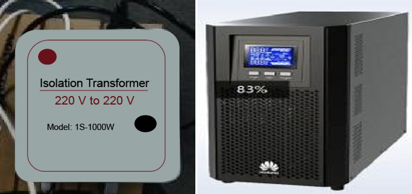
3. When the stability of the on-site power supply is not guaranteed, it is recommended to add an isolation transformer (recommended model: 1S-1000W/2000W) or UPS (recommended model: UPS2000-A-3KTTS) before the Genlock sync generator and LED controllers.
It is imperative that the capacity of the isolated power supply must meet the requirements of the sync generator and LED controller.
4. Double-shielded cables should be used for the Genlock connection.

¶ 4.5 Color Cast in Low Grayscale Range
Issue Description
1. Enabling Image Booster causes a color cast issue in low grayscale range.
2. Switching to high refresh rate mode causes a color cast issue in low grayscale range.
Cause of Issue
Incorrect parameters in the NCP file.
Solution
Contact the screen manufacturer or NovaStar technical engineers to obtain and upload the correct NCP file.
¶ 4.6 Unable to Display Offline Device in VMP
Issue Description
Unable to enter offline mode.
Cause of Issue
When running the calibration software, Cabinet Tool, and VMP simultaneously, these programs use the same port. As a result, offline devices are not visible in VMP.
Solution
- Check if the calibration software, Cabinet Tool, and VMP are running concurrently.
- Close the calibration software and Cabinet Tool.
- Restart VMP to resolve the issue.
¶ 4.7 Unable to Detect Online Device in VMP
Issue Description
VMP cannot detect any devices after connecting to a particular Windows computer.
Cause of Issue
Firewall settings on the computer are causing the issue.
Solution
- Verify if the device can be pinged. If not, ensure the device IP and subnet mask configurations align with the computer running VMP.
- Check the PC's firewall settings and disable the firewall.
¶ 5. Virtual Shooting Examples
¶ 5.1 Specifications and Applications of Virtual Shooting Studios
¶ Large xR Virtual Shooting Studio
Large xR virtual shooting studios are typically utilized for TV and film productions. These studios feature upright and sky LED screens, with real scenery often used on the floor based on filming needs.
In total, the screen measures over 500 square meters and is about 10 to 15 meters in height. (For example, both the upright screen and the sky screen have a size of 200 square meters.)
¶ Medium xR Virtual Shooting Studio
Medium xR virtual shooting studios are often utilized for filming commercial advertisements, web series, and smaller-scale events in addition to film and TV productions. These studios feature upright and sky LED screens, with real scenery often used on the floor based on filming needs.
In total, the screen measures from 200 to 500 square meters (mostly around 300 square meters) and is about 10 meters in height. (For example, both the upright screen and the sky screen have a size of 100 square meters.)
¶ Small xR Virtual Shooting Studio
Small xR virtual production studios typically utilized for filming commercial advertisements, web series, program activities, etc. These studios usually feature upright screens, floor tile screens, and backlight screens.
In total, the screen measures around 100 square meters and is about 7 to 10 meters in height. (For example, the upright screen and the floor tile screen have a size of 35 square meters, while the backlight screen has a size of 15 square meters.)
¶ 5.2 NovaStar Virtual Shooting Projects
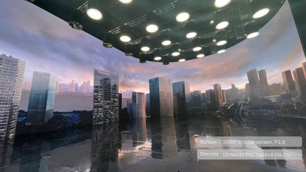
¶ Virtual Digital Studio - Hangzhou
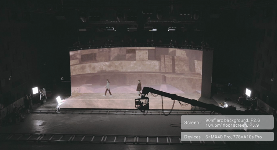
¶ xR Virtual Fashion Show - Chengdu
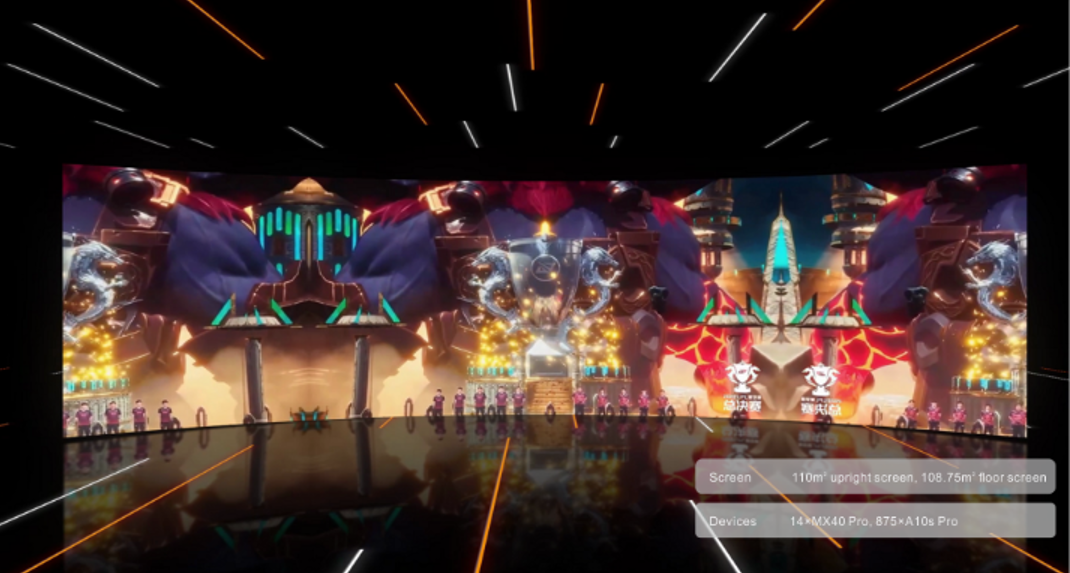
¶ 2022 LPL Summer Finals Opening Ceremony - Shanghai
We consistently enhance and refine the content of our Wiki articles.
If you find any mistakes or errors, please contact us.
Your continuous feedback and support will help us further improve our products and content.