¶ 1. Heat Characteristics
5G receiving card is designed in hardware to support a 5 Gbps transmission rate and a processing capacity of 512×1024 pixels. To achieve this, the chips handling image processing and data reception are of a higher specification. The higher hardware specification brings increased heat generation. We work closely with LED display (cabinet) manufacturers on this point, jointly ensuring a compliant cabinet heat-dissipation solution so that the 5G receiving card runs reliably over the long term. Heat dissipation is therefore not optional — it is a mandatory design requirement that the cabinet must fulfill. The key heat-generating components are listed below (ambient temperature 25°C):
| Key component | Power | Junction temp. limit | Dissipation method |
| FPGA | 5 W | 85°C | Shell-contact cooling (via thermal pad to aluminum platform/shell) |
| PHY (on HUB board) | 2.5 W | 85°C | Shell-contact cooling + aluminum heat-sink fin |
| SDRAM | 0.5 W | 85°C | Cooled together with the receiving card |
Note:
the figures above are per-chip power. The actual operating temperature inside the cabinet is higher than ambient. If the heat path is incomplete, chip temperature can exceed the 85°C limit within a short time and damage the components.
¶ 2. Heat-Dissipation Structure
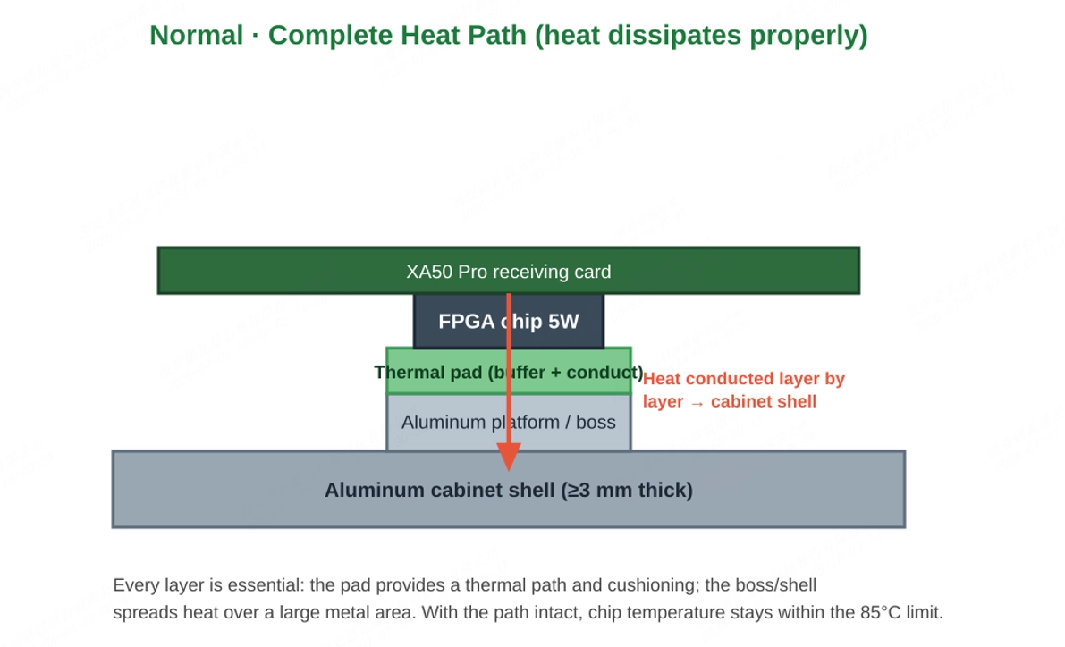
The XA50 Pro uses shell-contact cooling: chip heat is conducted layer by layer through thermal materials to the metal cabinet shell, then dissipated to the environment over the large shell area. The complete heat path consists of the following three links, none of which may be omitted:
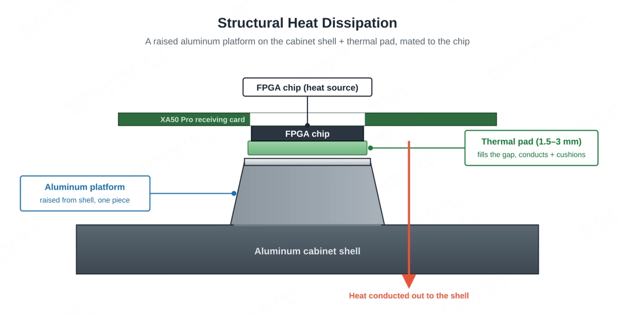
- Aluminum platform / shell: the aluminum plate must be at least 3.0 mm thick with an area larger than 250×250 mm. If the cabinet itself is aluminum with sufficient thickness and area and can conduct heat directly, a separate plate may not be needed.
- Thermal pad (thermal silicone): fills the gap between the FPGA chip and the aluminum platform (recommended gap 1.5–3 mm; the thinner the pad, the better the conduction). It serves as both a thermal path and a cushioning layer.
- PHY heat-sink fin: the PHY chip on the HUB board needs a separate aluminum heat-sink fin matched to its size, with corresponding screw holes reserved on the HUB board.
¶ 3. Notes for Part Replacement
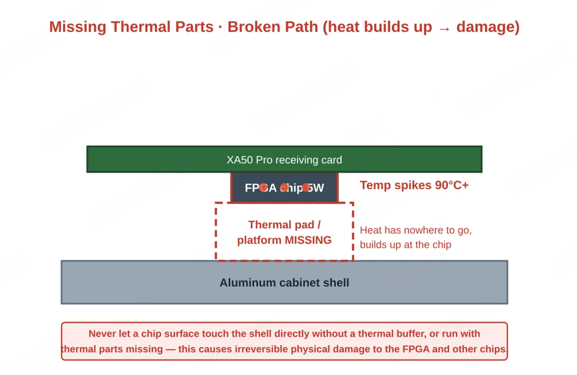
When internal components such as the receiving card or HUB board need to be replaced due to damage, the disassembly process will involve the thermal pad and heat-sink block (fin) on the FPGA / PHY. If the thermal parts are not reinstalled after replacement, the heat path is cut off, heat keeps building up at the chip, the temperature can rise above 90°C, and the internal components might be eventually damaged.
The surface of the FPGA (or other heat-generating chips) should not directly contact the enclosure; a proper thermal interface material must be used as a buffer. In addition, the card should not be operated without the required thermal components installed. Otherwise, heat dissipation will be impaired, which may lead to elevated chip temperature, triggering the receiving card’s protection mechanism and causing abnormal display behavior. In some cases, this may result in permanent damage.
Please note:
before shipment, every 5G receiving card undergoes strict heat-dissipation design control. With all thermal parts in place, the factory cabinet's thermal design keeps the chips operating within a safe temperature range.
For any service that opens the cabinet or replaces internal components (especially the HUB board or receiving card), confirm each of the following items before powering on:
- The thermal pad is reinstalled, fully in contact with the chip and the aluminum platform — no omission, no damage, no misalignment.
- The aluminum platform / heat-sink block is installed and secured, with thermal material filling the gap to the shell.
- The heat-sink fin for the PHY chip on the HUB board is installed and locked.
- The FPGA chip surface is not in direct hard contact with any metal part (a thermal buffer material must be in between).
- The DDR socket orientation (front/reverse) is correct, so the FPGA faces the cabinet's heat-dissipation back.
- After powering on, observe the operating status and, where possible, confirm the cabinet temperature is normal.
¶ 4. Solution Confirmation & Technical Support
To avoid heat-related problems later in use, we recommend defining the heat-dissipation solution together with the LED display manufacturer at the cabinet design / procurement stage. If you need help confirming the solution, please provide the following information and we will carry out a feasibility analysis and give recommendations:
- The chip cooling method: direct shell-contact cooling, or an aluminum plate first and then shell contact;
- The relevant temperatures in use, including the temperature inside the cabinet and the ambient temperature outside.
We consistently enhance and refine the content of our Wiki articles.
If you find any mistakes or errors, please contact us.
Your continuous feedback and support will help us further improve our products and content.