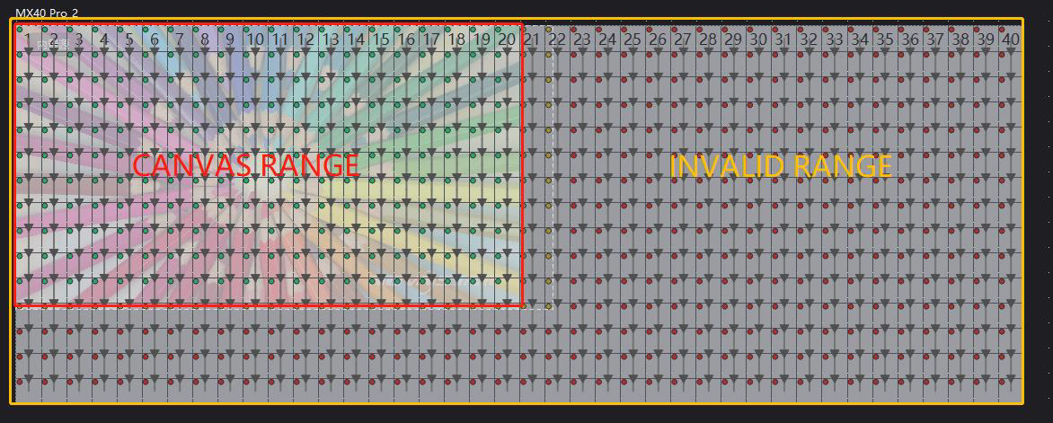
Since the integration of control system and layer configuration system in VMP, there is a concept of effective boundary in the cabinet configuration, and this effective boundary is the canvas.
The canvas is actually the maximum range that the controller can effectively display, and its size is only related to the refresh rate and resolution, while any cabinet outside the canvas range will output the black image.
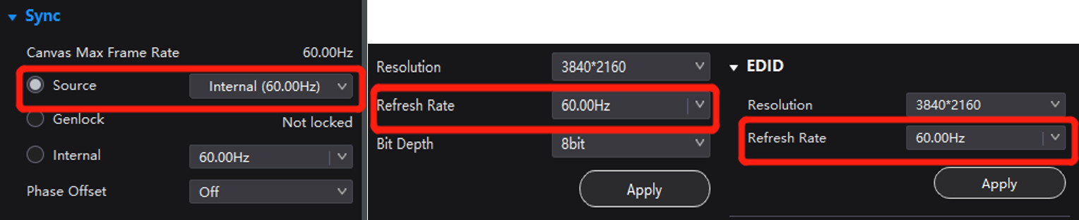
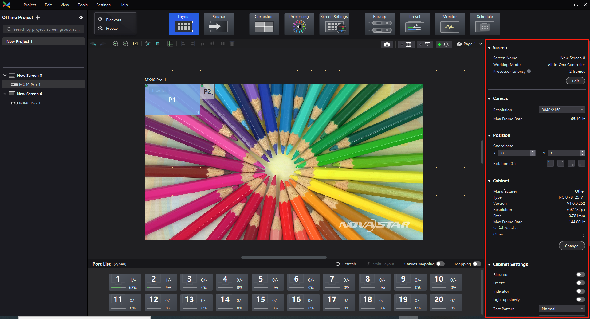
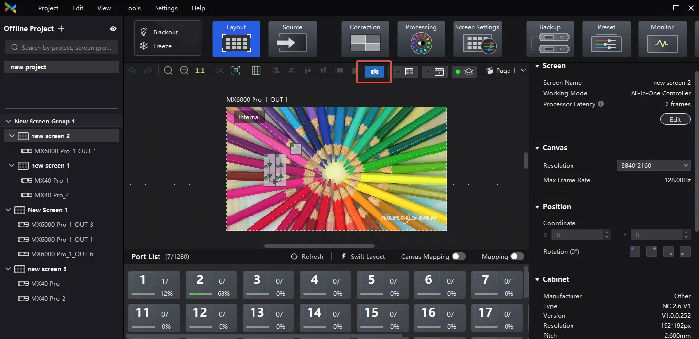
The screen size can be set in the right function area. As the screen resolution changes, VMP software will automatically calculate the maximum frame rate that can be output under the current screen size.
Note:
At this point, it is important to set a consistent input source frame rate on the Source interface and synchronize the output with the video source.
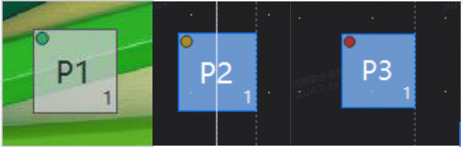
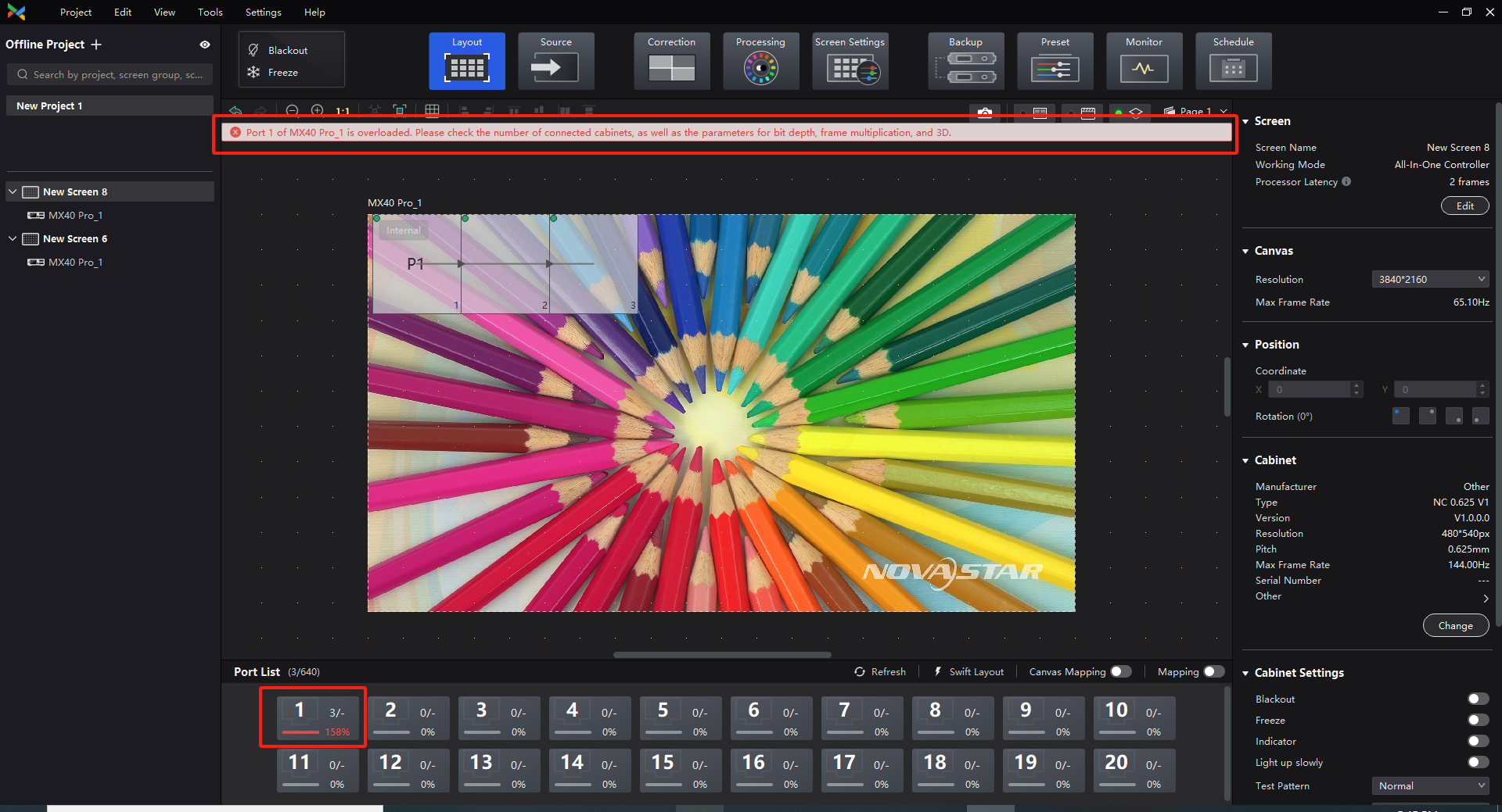
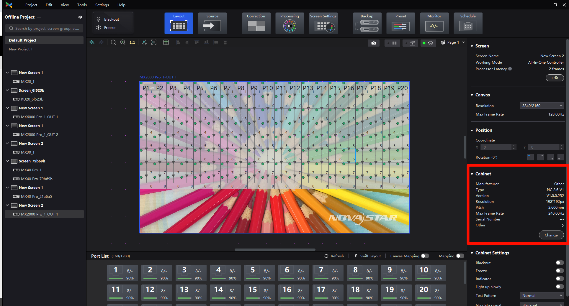
Based on the above concept of the canvas, there are a total of three types of cabinet states under this service: the green-indicator, the yellow-indicator, and the red-indicator
In this case, the green indicator represents that the cabinet is within the canvas range and there is normal image output; the yellow indicator represents that the cabinet is partly inside the canvas range, and only the inside part has image output; the red indicator means that the cabinet is completely outside the canvas range and there will be no image output.
The Port List displays the port information of the selected device, including the load ratio under each port and the number of connected cabinets. When the total number of connected cabinets under a certain port exceeds the load capacity of a single port, the user will be prompted to modify the actual number of loaded cabinets.
By clicking on the cabinet on the topology area, the corresponding functions and information of the cabinets will be displayed on the function area, such as screen, canvas, cabinet position, cabinet settings, optical port settings, etc.
Click on the single port to connect the screen, and the software will automatically set all the cabinets under that port until the single port screen connection is completed.
Clicking on different cabinets in the topology area will also cause the function area to display the corresponding cabinet information and related function settings.
Note:
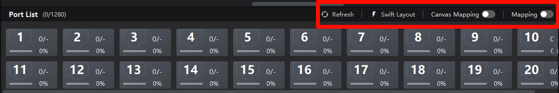
When the port status is displayed abnormally after adjusting the port connection, users can refresh the port status in the upper right corner of the port list.
¶Single-port Configuration and No rectangular calculating limitation
After clicking on any port in the port list, drag it freely on the topology area to complete the screen connection under a single port.
In addition to conventional screen connection, the COEX series no longer has rectanglar calculating limitation, and users can freely complete the cabinet layout on the screen.
This function requires a cabinet of the same size under the controller or output card.
In addition to the conventional screen connection under a single port, VMP software also has a swift layout function. After clicking on any port in the port list, click the swift layout button to complete the screen connection of all ports at once.
After the screen connection, in addition to selecting the cabinet in the topology area and directly dragging it to change the cabinet layout, you can also modify the cabinet coordinates in the function area to complete more refined cabinet layout changes.
At the same time, for some special scenarios, VMP software also supports 90-degree multiple rotation of the selected cabinet.
Note:
The rotation function requires hardware support. For more information, please contact FAE.
If the hardware supports it, but there is no rotate button on the software, it is a mismatch of the acceptor card firmware, and you may need to contact FAE for the firmware.
Cabinet information from the NCP file, if there is no NCP file inside the cabinet, the information will be partially missing.
The change button is for offline mode to facilitate the switching of different specifications of the NCP analog screen, online mode needs to enter the maintenance interface to send down the NCP to modify the specifications of the cabinet.
Left-click to select the Ethernet port, click the custom group NCP, and click the edit button; then, you can change the specification.
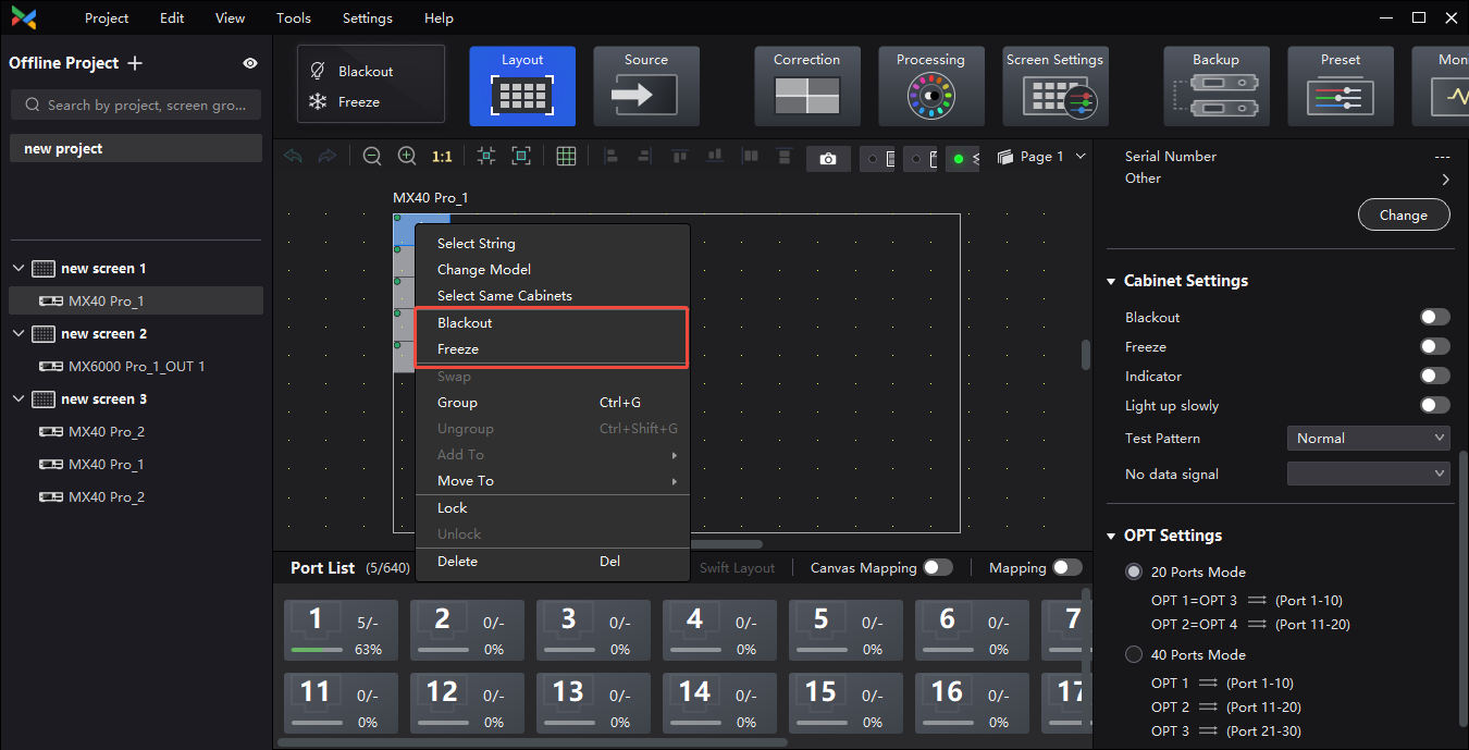
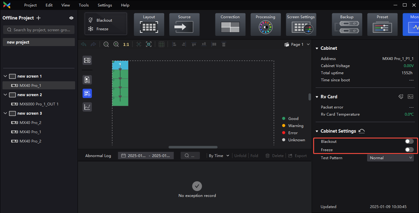
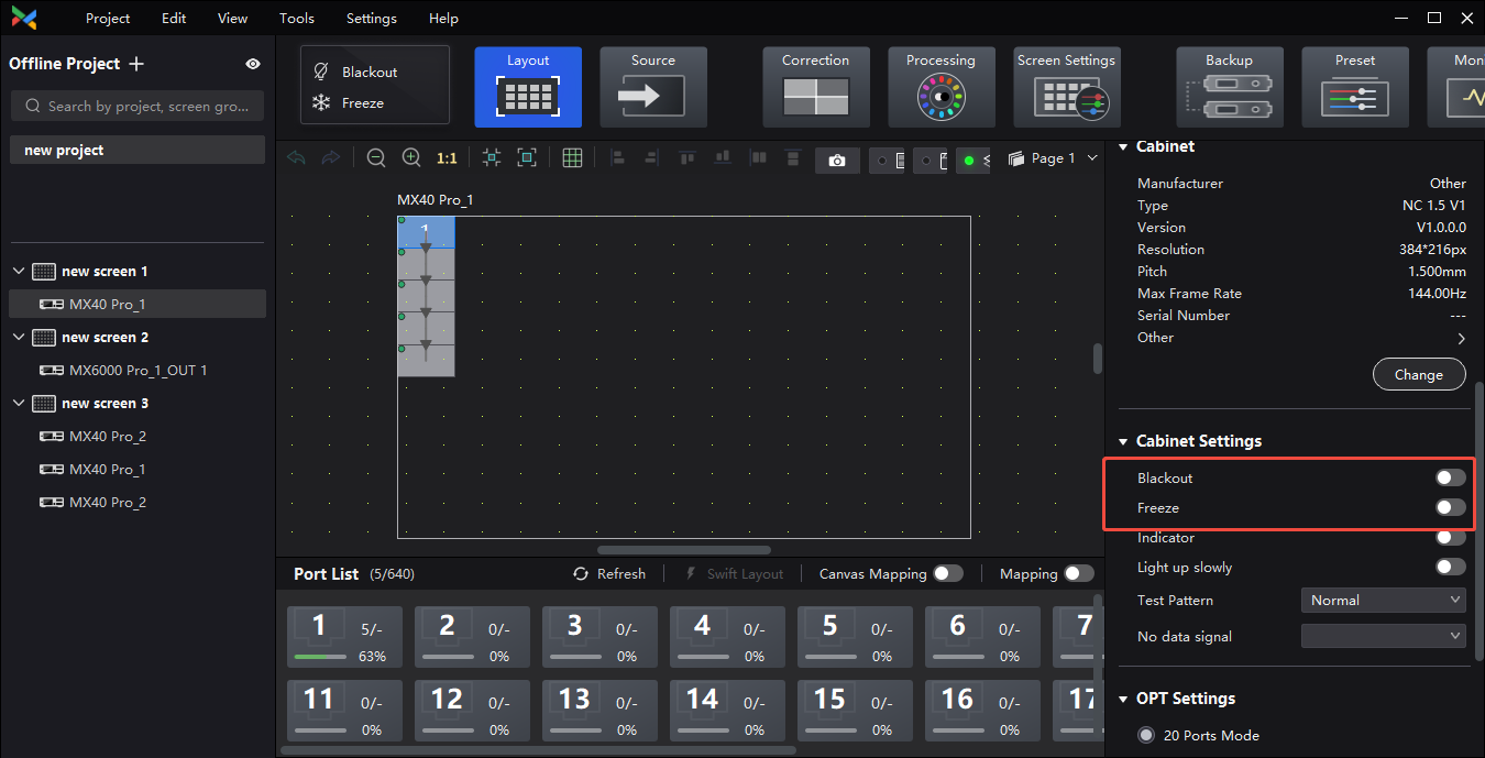
Right-click on the cabinet group/cabinet and select Blackout or Freeze in the pop-up window or select Blackout or Freeze on the right side of the Layout or Monitor interface, at which point the blackout/freeze operation will be performed at the receiving card level;
Option to show or hide the coordinates ruler. Users can view the cabinets' positioning and overall dimensions through coordinate ruler, as well as the position and scale relationships between the cabinets and the canvas.
Click the "Coordinates Ruler" button in the screen list. Ctrl+R can also show or hide the coordinates ruler.