In order to increase the adaptability of COEX system to projects and improve the image quality, VMP software provides users with multiple functions related to image quality and output adjustment in the screen settings interface.
¶ Image Quality Adjustment
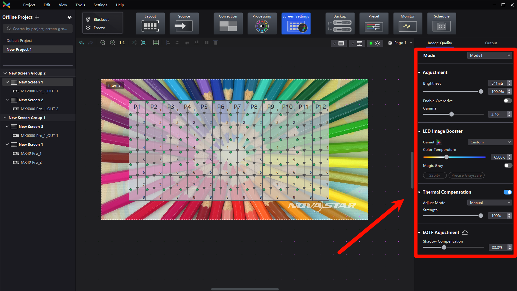
After clicking on Screen Settings in the top function tabs, click on Image Quality above the function area on the right side of the interface, and the function area will display the settings related to image quality improvement. They are listed from top to bottom as Multi-Mode, Brightness and Gamma Adjustment, Image Booster, Thermal Compensation, and EOTF Adjustment.
¶ Multi-Mode
There are two ways to reduce the brightness, one is to reduce the global brightness, the other is to reduce the current gain of the driver chip, and the way to reduce the current gain can reduce the loss of grayscale in the case of achieving the expected brightness, providing a better display effect.
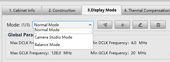
Multi-mode can also be applied to the use of XR and VP shooting scenes, the scene can switch different display modes according to the content of the shooting material, the effect of the shooting mode has significantly improved the shooting effect of low light material, and can greatly improve the chip low gray refresh, reduce the scan line problem of low gray shooting scenes.
Select a controller from the project list and then select Screen Settings.
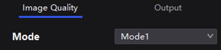
On the Image Quality tab, select a mode based on the application scenario to let the screen have the optimal display effect.
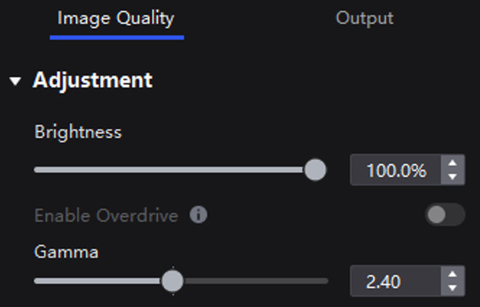
¶ Adjust Brightness and Gamma
Manually adjust the screen brightness and gamma to change the screen brightness and chroma performance in real time, and enable or disable brightness overdrive as needed.
If brightness correction has been done for the screen, the screen brightness can be adjusted in nits. Otherwise, it can be adjusted only in percentage.
Select a controller from the project list and then select Screen Settings.
On the Image Quality tab, adjust the brightness and gamma value, and enable or disable Brightness Overdrive as needed.
¶ Brightness Limit
In the Screen Settings-Image Quality part, click the button beside Brightness. then you can set the brightness limit.
Addressing screen brightness limitation requirements for overcurrent protection scenarios.
¶ Brightness Component

In the Screen Settings-Image Quality part, under Brightness component, you can adjust the W/R/G/B component.
Correcting color differences across different cabinet types under the same brightness.
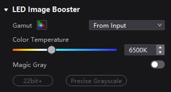
¶ Image Booster
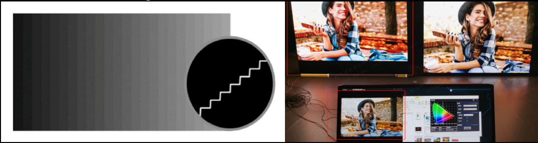
22bit+: Improve the LED screen grayscale by 64 times to avoid grayscale loss due to low brightness and allow for a smoother image with more details in dark areas.
Precise Grayscale: Individually correct the 65,536 levels of grayscale (16bit) of the driver IC to fix the display problems at low grayscale conditions, such as brightness spikes, brightness dips, color cast, and mottling.
Color Management: Support standard (Rec.709 / DCI-P3 / Rec.2020) and custom color gamuts, enabling more precise colors on the screen.
Select a controller from the project list and then select Screen Settings.
Select the Image Quality tab on the Screen Settings page. In the LED Image Booster area on the right, select an output color gamut from the Gamut drop-down list.
The output gamut options include standard gamuts, custom gamuts, the original screen gamut and the input gamut (From input).
To set the custom gamut, click the color gamut icon, select a gamut in the properties area on the color gamut diagram, and adjust the red, green, blue and white parameters based on the selected gamut. The custom gamut name can be changed.
Drag the slider to adjust color temperature.
Enable or disable Magic Gray as needed.
¶ Thermal Compensation
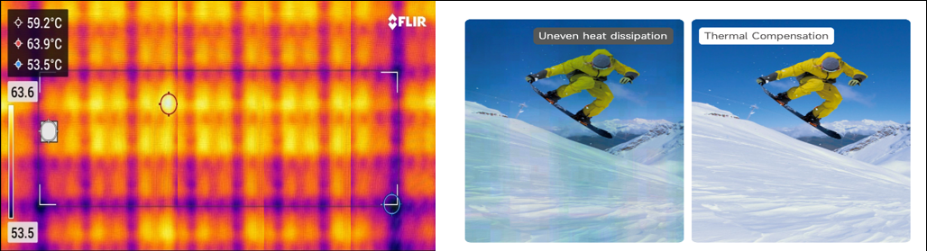
The thermal compensation function is mainly used to solve the redness and blueness on the edge of the module or cabinet. This issue is caused by the uneven fan heat.
Sensor solution introduction: Add a temperature sensor in the LED cabinet, the sensor obtains the temperature of each cabinet in real time and passes it back to the control system, the control system automatically adjusts the compensation coefficient of each cabinet in real-time according to the temperature.
Dynamic thermal compensation solution: The control system based on the use of the screen, according to the video source image, brightness, and other information, automatically predicts the thermal change law of the screen, intelligent algorithm, and automatic adjustment of compensation coefficient.
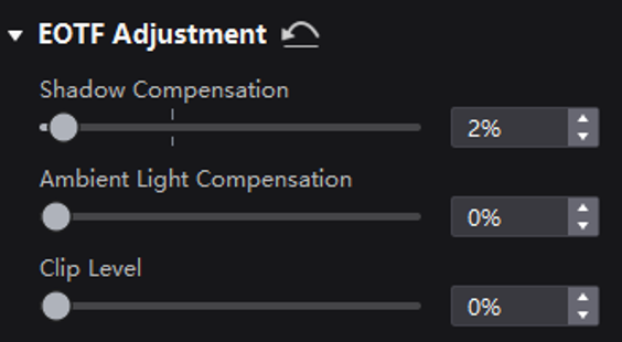
¶ HDR and EOTF
The supported adjustment parameters depend on the HDR settings.
Select a controller from the project list and then select Screen Settings.
On the Image Quality tab, drag the sliders to adjust the values of Shadow Compensation, Ambient Light Compensation, and Clip Level.
¶ Output Adjustment
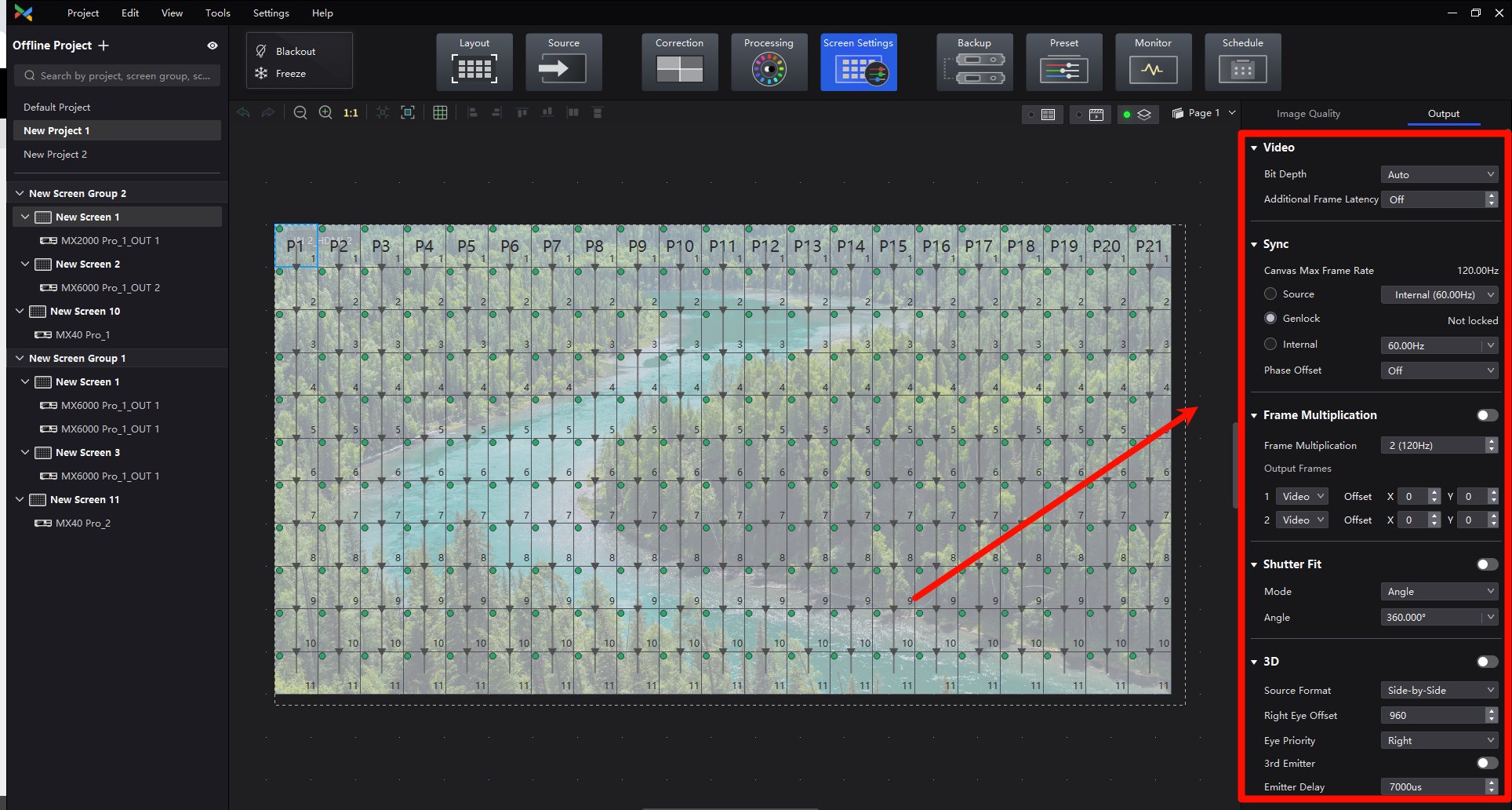
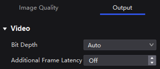
¶ Video Parameters
Select a controller from the project list and then select Screen Settings.
In the Output tab, select an option from the drop-down list of Bit Depth.
If Auto is selected, the output bit depth is the same as the input bit depth.
Set a value for Additional Frame Latency.
When the controller is used with high-latency devices and there is a need to increase the latency, you can adjust the value for Additional Frame Latency.
¶ Sync Parameters
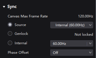
Select a controller from the project list and then select Screen Settings.
Select the Output tab.
Select a synchronization signal for the display frame rate and set the phase offset.
- Canvas Max Frame Rate: This displays the maximum frame rate of the current output card's canvas. If all canvases have the same maximum frame rate, it will show the value. If the frame rates are different, it will display Mix.
- Source: Sync with the frame rate of the active source.
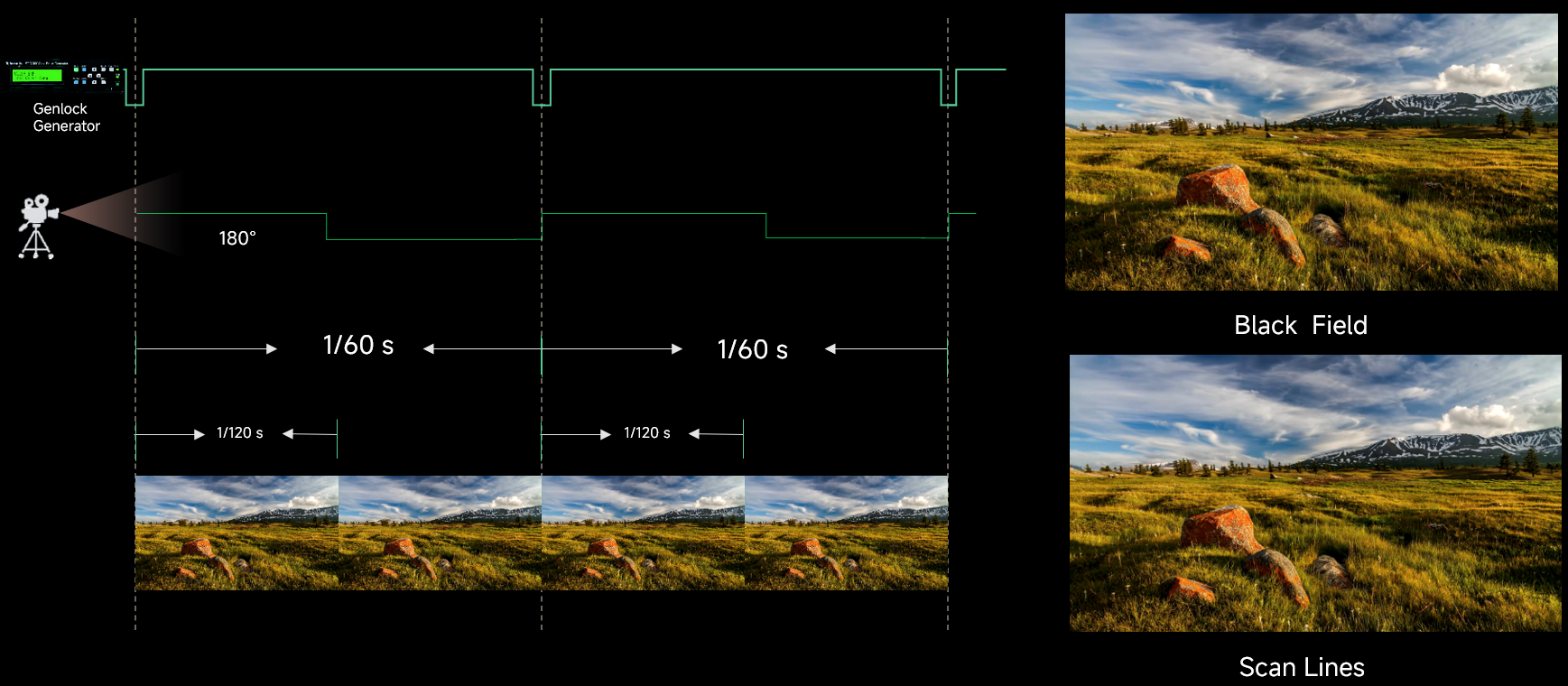
- Genlock: Sync with the frame rate of the Genlock signal. When the shutter fit function of the controller is effective, please select this option. In addition, the controller and the camera need to use the same Genlock signal generator.
- Internal: Sync with the frame rate of the controller's internal clock.
¶ Frame Multiplication
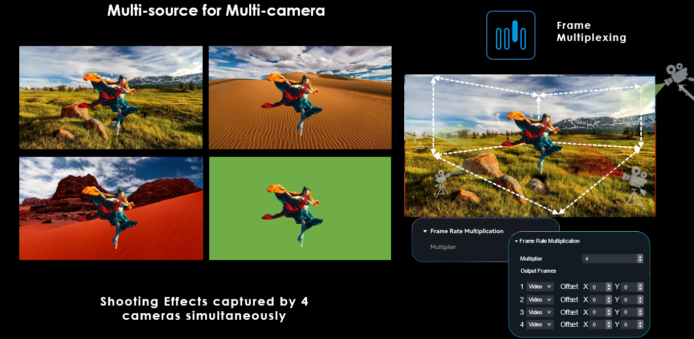
Outputs images that are captured from multiple shooting angles with different backgrounds at the same time. Solid green backgrounds can also be inserted to allow for easy post-production adjustments. Supports high frame rates of up to 240 Hz. This feature accommodates multi-angle camera shooting to improve the screen performance under the camera.
- Frame multiplication, low latency, and 3D cannot be enabled at the same time.
- MX6000 Pro and MX2000 Pro are capable of supporting a max frame rate of 480 Hz when using the A10s Pro and CA50E receiving cards.
- MX40 Pro is capable of supporting a max frame rate of 240 Hz when using the A10s Pro receiving card.
- The specific maximum frame rate that can be set is related to the hardware configuration of the screen.
Select a controller from the project list and then select Screen Settings.
Select the Output tab and set Frame Multiplication to on.
Set the number of frames and the display mode of each frame.
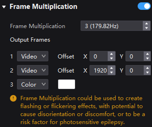
Take the above figure as an example. The parameters are described as follows:
- Frame Multiplication: After the current frame rate (59.94) is multiplied by 3, it is 179.82 Hz. Three frames are output in 1/59.94 seconds.
- Video: The first and second frames display the input source image. The first frame displays the image from the coordinates (0, 0) and the second frame displays the image from the coordinates (1920, 0).
- Color: The third frame displays a pure white image.
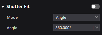
¶ Shutter Fit
Automatically adjusts the driver IC parameters according to the camera shutter angle to fix problems of black lines, grayscale addition, and grayscale loss during camera shooting in xR scenarios.
It requires that the sync signal must be Genlock and the controller and camera need to use the same Genlock signal generator.
Select a controller from the project list and then select Screen Settings.
Select the Output tab and set Shutter Fit to on.
Set the relevant parameters.
¶ 3D
The COEX series products adopt active shutter 3D technology to be 3D-ready. This is achieved by increasing the refresh rate of the screen, splitting the image into two distinct halves for the left and right eyes. These two sets of images are displayed in rapid succession, alternating seamlessly. In tandem, a 3D emitter synchronizes with the 3D glasses via a precise timing signal. This signal ensures that the glasses alternate between blocking each eye, permitting each to view their corresponding images precisely when intended. This process creates stereoscopic 3D images.
Select a controller from the project list and then select Screen Settings.
Select the Output tab and set 3D to on.
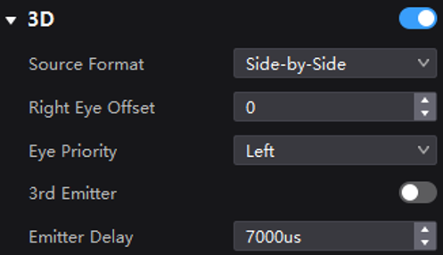
Set the related parameters.
- Source Format: Set the format of the 3D video source. Set the format to Side-by-side, Top-and-Bottom or Frame Sequential according to the format of the accessed video source.
- Right Eye Offset: Set the start position of the right eye image. When the video source format is side-by-side or top-and-bottom and the left and right eye images are provided, this parameter can be set.
- Eye Priority: Set which image is sent first, the right eye image or the left eye image. Wear the 3D glasses to watch the display. If the display is abnormal, set the parameter value to the other one. If the display is normal, the setting is done.
- 3rd Emitter: When a third-party 3D signal emitter is used, set the switch to on.
- Emitter Delay: Set the delay time of sending the synchronization signal from the 3D signal emitter to the 3D glasses. This setting ensures that the switching between the left and right eye images of the 3D glasses is in sync with the switching between the left and right eye images on the display. This parameter is applicable to both the NovaStar and third-party emitters.
- For more COEX 3D information, please click this link: 3D Solution
We consistently enhance and refine the content of our Wiki articles.
If you find any mistakes or errors, please contact us.
Your continuous feedback and support will help us further improve our products and content.