¶ The User Interface

- VMP Software Downloads → Software Page(The loading may take a few minutes)
¶ Language and Preferences
Users can adjust the software language and temperature scale.
¶ Device Management

In version 1.4.0. and later VMP, the working flow of device management, is as follows: project, screen group, screen, and device.
In addition to the new project, screen group, and screen that can be created by the plus sign at the top of the device list, the user can also move the device, screen, or even the screen group freely among different projects by dragging and dropping.
Notes:
In online mode, any successfully connected processor will automatically appear in the device list. If you are using offline mode, new devices can be added using the plus sign at the top of the device list.
In order to improve the usability of VMP's group management function, in addition to retaining the original group management design, VMP has added a new group coefficient management function since version 1.4.0.
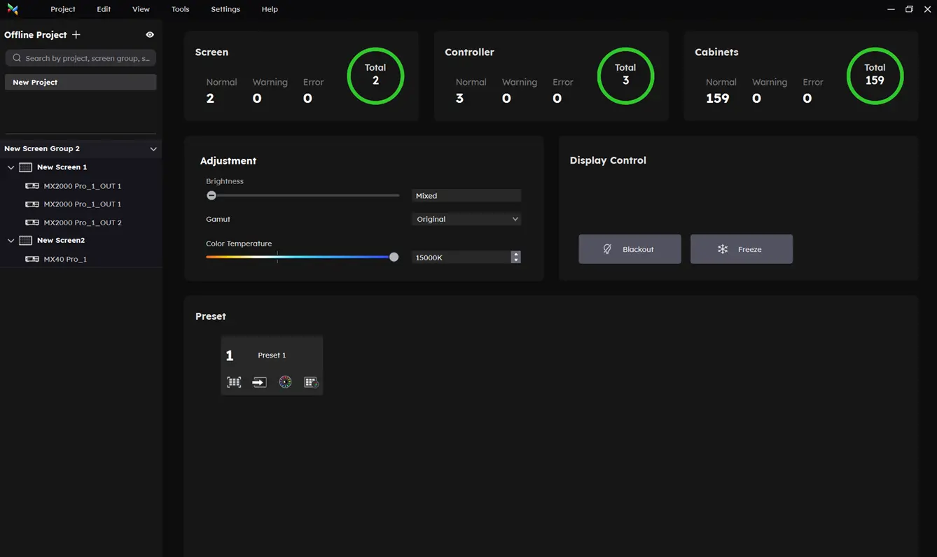
In version 1.5.0, in addition to the basic screen control available in previous versions, users can now view the basic information of screens, controllers, and cabinets through the screen group management interface and perform preset switching operations.
By selecting a project or screen group, you can uniformly control the screens within the group/project and perform various batch operations.
- View the number of screens, controllers, and cabinets, along with their current operating status.
- Adjust image quality settings, such as brightness, color temperature, and color gamut.
- Control the display, including functions like blacking out the screen or freezing the image.
- Easily switch between saved preset configurations.
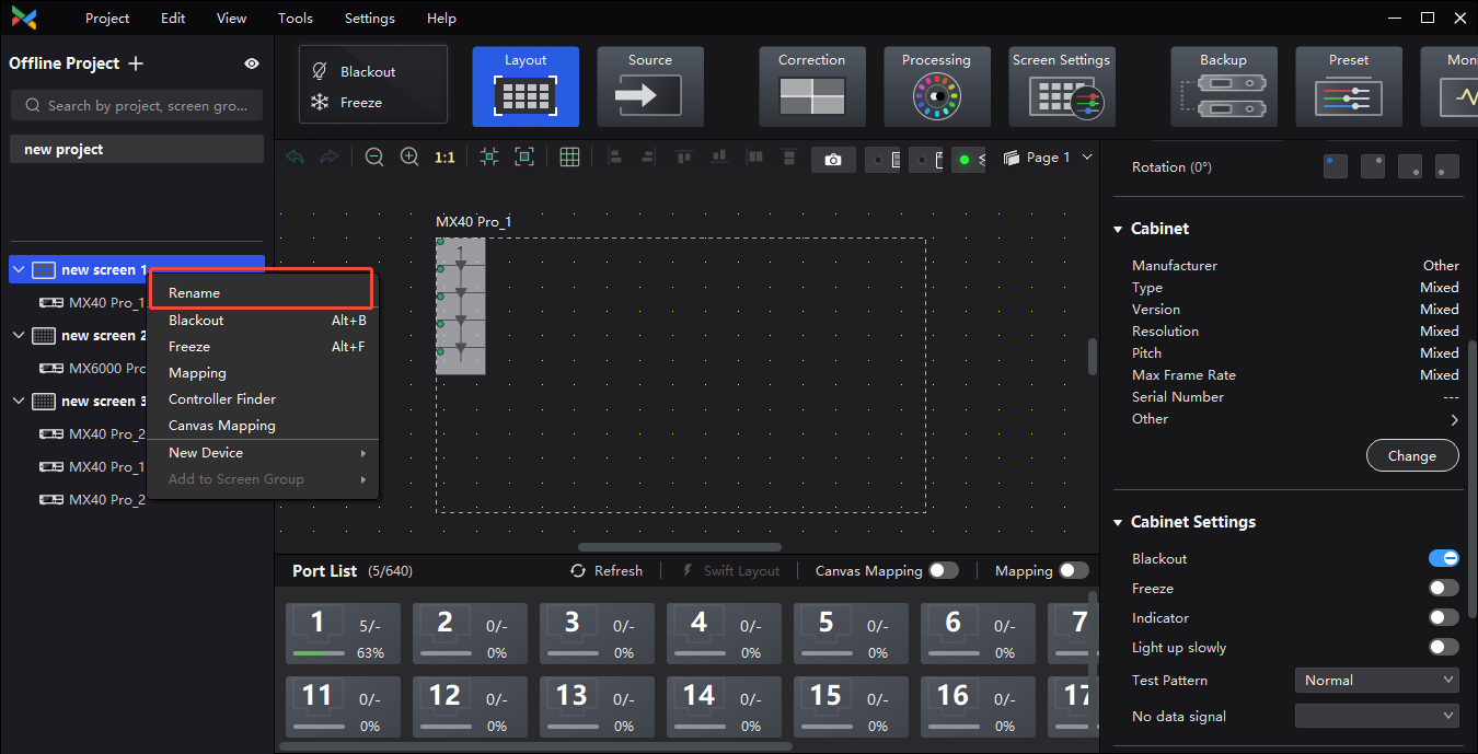
¶ Rename device/screen/screen group/project
Right-click, select Device/Screen/Screen Group/Project and choose Rename in the pop-up window.
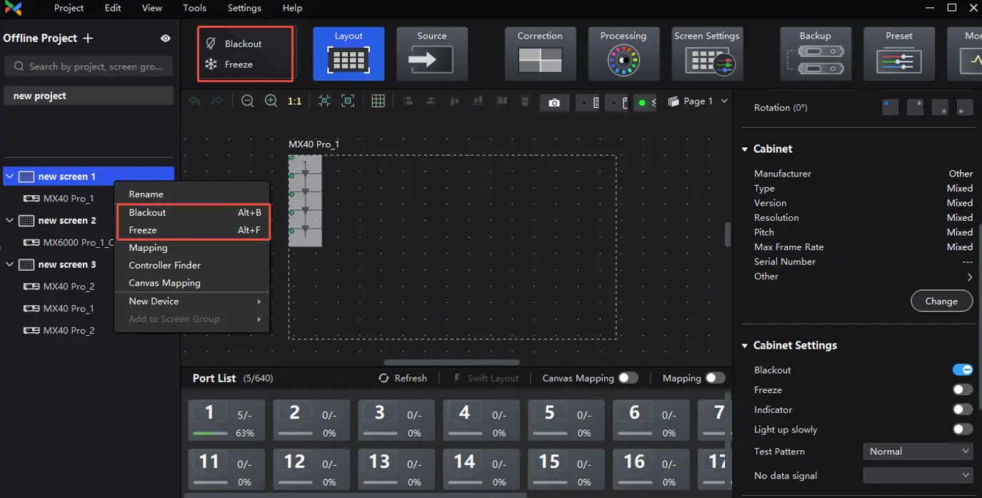
¶ Black out or freeze project/screen group/screen/device/cabinet group/cabinet
Right-click Project/Screen Group/Screen/Device and select Blackout or Freeze in the pop-up window or select Blackout or Freeze in the upper left corner of the interface, then the black screen/freeze operation will be performed at the controller level;
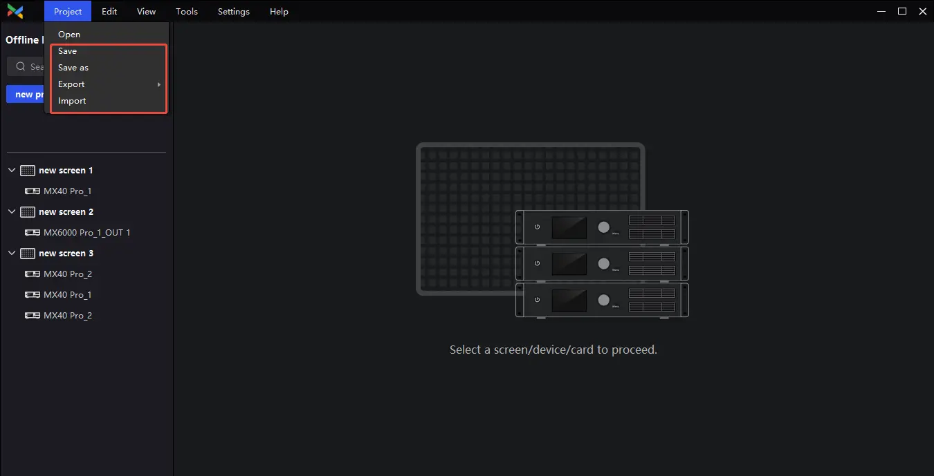
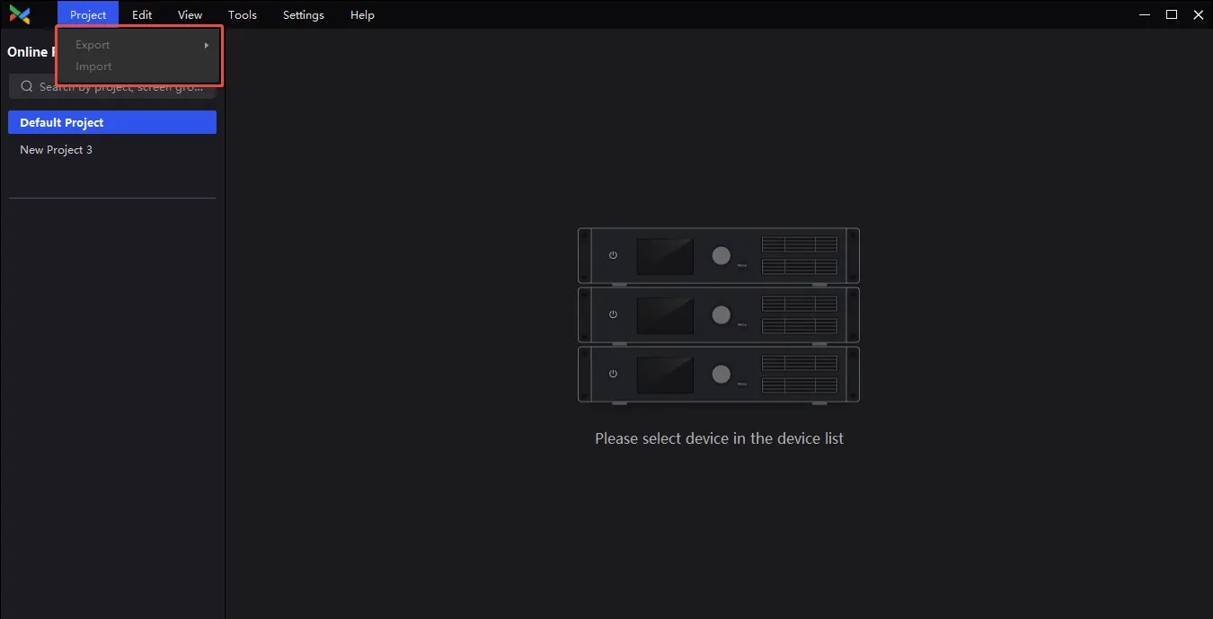
¶ Import/export/save/save as project
Right-click and select the project in the pop-up window or click on the project in the navigation bar and select Import/Export/Save/Save As (the last two are only available offline).
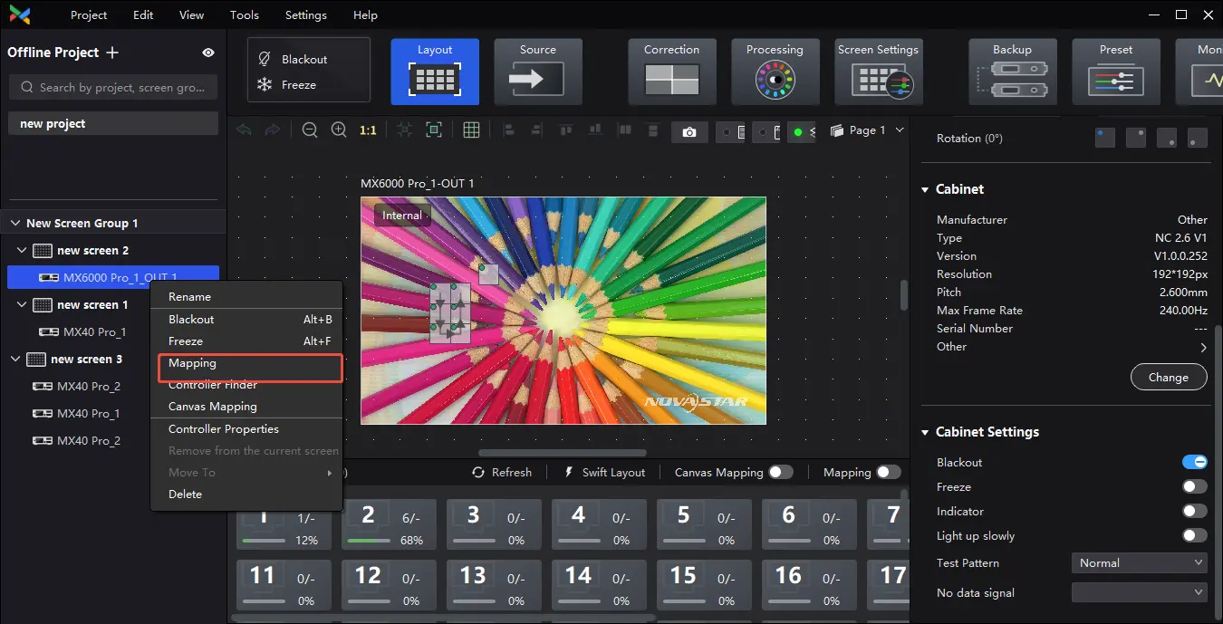
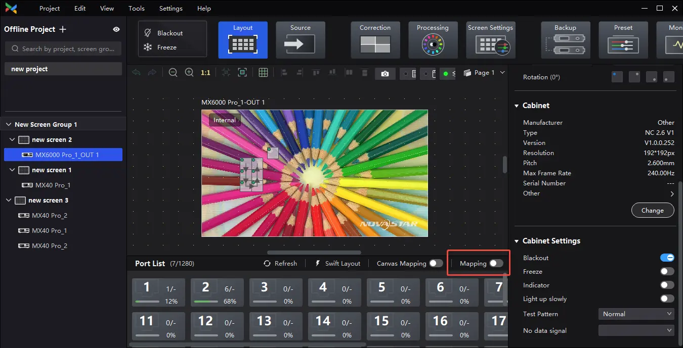
¶ Screen/device mapping
Right-click on the screen/device and enable mapping in the pop-up window or in the upper right corner of the port list.
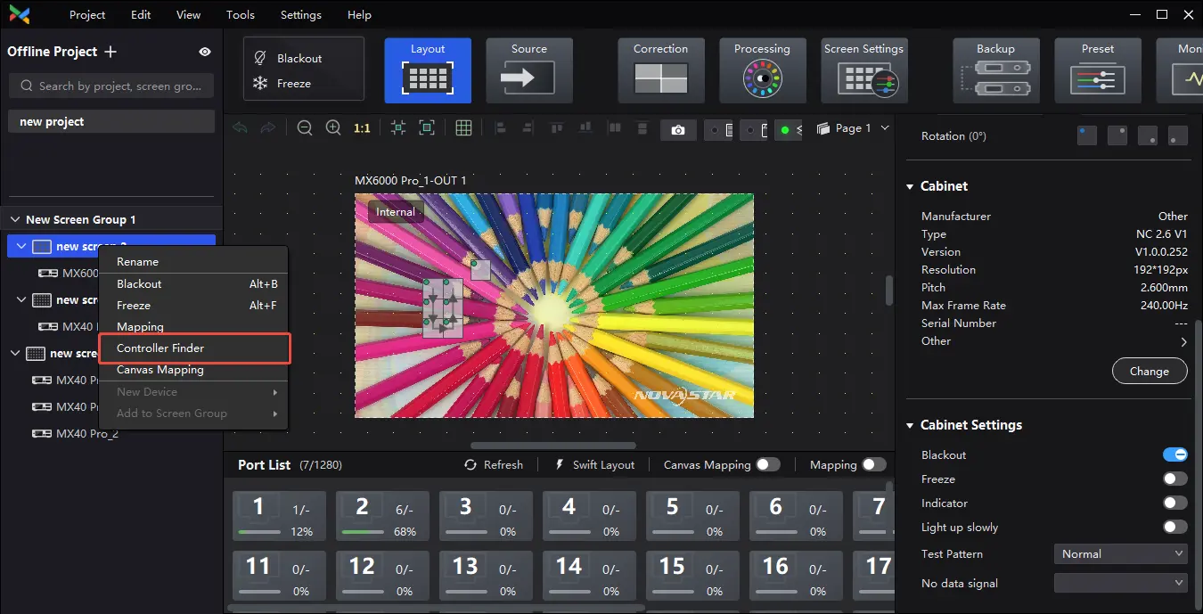
¶ Screen/device/ Controller Finder
Right-click on the screen/device and select Controller Finder in the pop-up window.
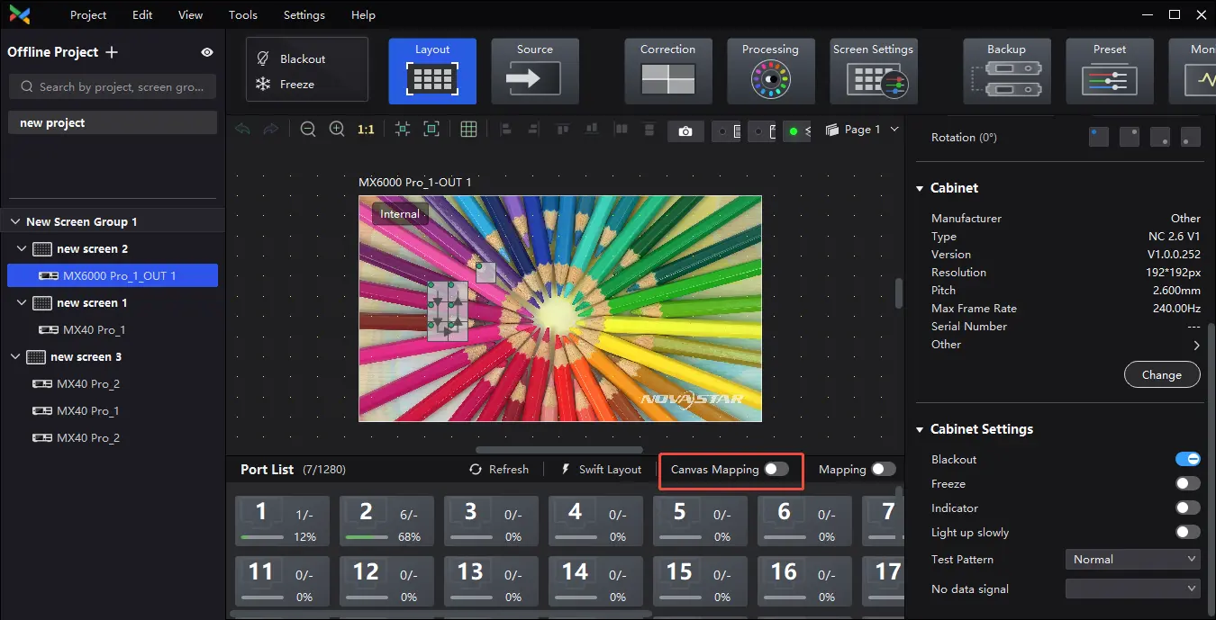
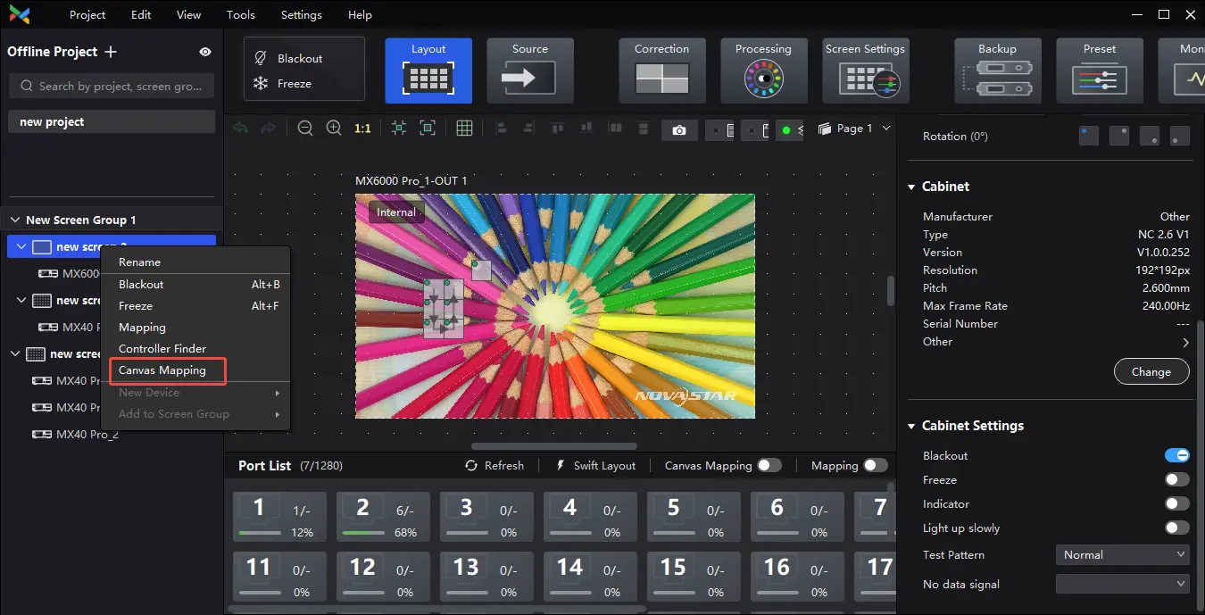
¶ Screen/device Canvas Mapping
Right-click on the screen/device and select Canvas Mapping in the pop-up window.
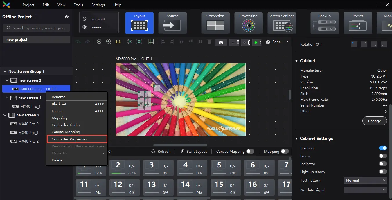
¶ Controller Properties
Check for device IP, MAC address, firmware version, time, device log, time since boot, bandwidth, and free EMMC capacity.
Right-click the device and select Controller Properties in the pop-up window. Then you can view the device IP, MAC address, firmware version, time since boot, etc.
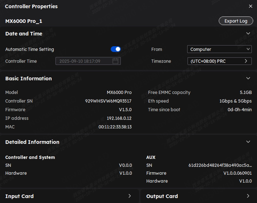
Date and Time
Auto Sync:
1. Toggle on Automatic Time Setting. You can choose to sync from either the Computer or an NTP Server.
If you select Computer, the controller's time will be synchronized with the control computer's time.
If you select NTP Server, you can manually enter the NTP server address and select your timezone and daylight saving settings to obtain the correct time for the chosen timezone.
2. Click Sync Now to complete the time setting.
Manual Adjustment:
Toggle off Automatic Time Setting and click Controller Time to manually adjust the time.
Basic Information
Check the controller model, SN, firmware version, IP address, MAC address, etc.
Detailed Information
Click the play button to expand the panel and check the detailed controller hardware and software information.
Input/Output Card Information
Check the input/output card name, model, SN, firmware version, hardware version and other information when connecting to card-based controllers (MX6000 Pro and MX2000 Pro).
Export Logs
Click Export Log, select a location, set the file name, and click Save.
¶ Move in/out of the screen
This function should be used under the same screen, the device model, version, and output card type must be consistent.
Right-click on the device and select Move In/Out Screen in the pop-up window.
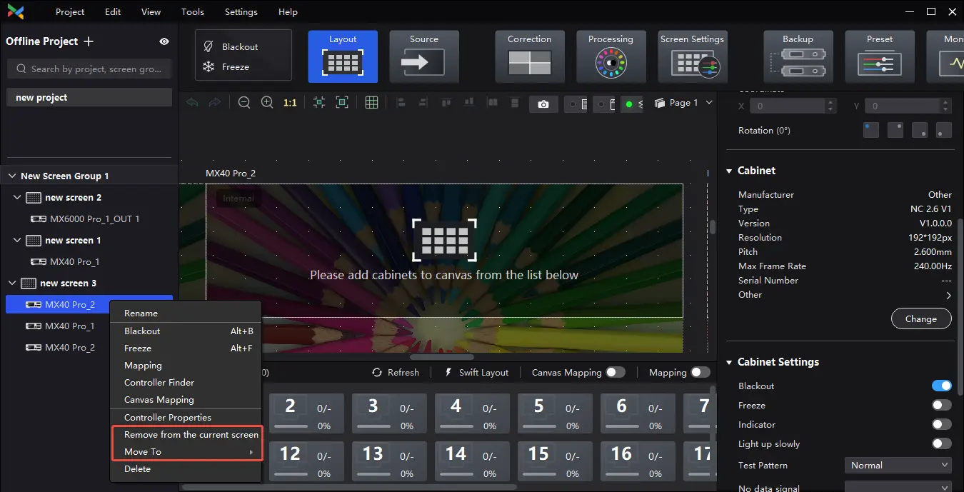
Left-click to select the device and drag it to the corresponding screen.
¶ Peripherals Management
VMP supports detecting all 3D emitters, multifunction cards, and light sensors connected to the project controllers, as well as enabling power control through the multifunction cards.
- 3D emitters: EMT200 Pro
- Multifunction card: MFN300
- Light sensor: NS060
¶ Notice
When system backup is set, only the primary controller/card/Ethernet port can detect and read information from multifunction cards and light sensors. Backup controller/card/Ethernet port does not support detecting or reading this information.
It is recommended to connect the multifunction card to port 1 of the controller. For the multifunction card MFN300-B V4.4.2.0 and above, connect to any of the first 16 ports of the controller.
If multiple controllers with light sensors are connected to the same screen and are placed in environments with different brightness levels, ensure proper communication between the controllers when adjusting screen brightness via the brightness strategy table. Otherwise, inconsistencies in screen brightness may occur.
¶ Related Information
- Light sensor ambient brightness rules: The light sensor checks the brightness every 10 seconds and adjusts every minute. During adjustment, it discards the highest and lowest values from the five most recent readings and calculates the average to determine the ambient brightness.
- A single controller can connect to multiple multifunction cards, with each card supporting up to four light sensors. When multiple light sensors are connected, the average ambient brightness from all sensors is used.
¶ Operating Procedure
1. Select a project from the project list.
2. In the Peripheral section of the project list, you can check the 3D emitters and multifunction cards connected to all the controllers within the project, as well as the light sensors connected to the multifunction cards.
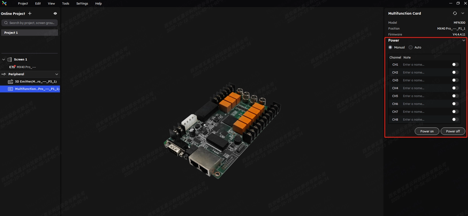
3. Select a peripheral to view its information in the properties area on the right.
- 3D emitter: You can view the model, position, and firmware version.
- Multifunction card: You can view the model, position, and firmware version.
- Light sensor: You can view the position and ambient brightness.
Light sensor ambient brightness rules: The light sensor checks the brightness every 10 seconds and adjusts every minute. During adjustment, it discards the highest and lowest values from the five most recent readings and calculates the average to determine the ambient brightness.
4. Perform power control operations as needed.
Select a multifunction card and set the power control mode in the properties area on the right. You can choose between the auto and manual mode. You can also click Power on or Power off to control the state of all power channels.
- Manual mode: Set the state of each individual power channel.
- Auto mode: Different start and shutdown times can be set for each power channel, with default times retrieved from the multifunction card.
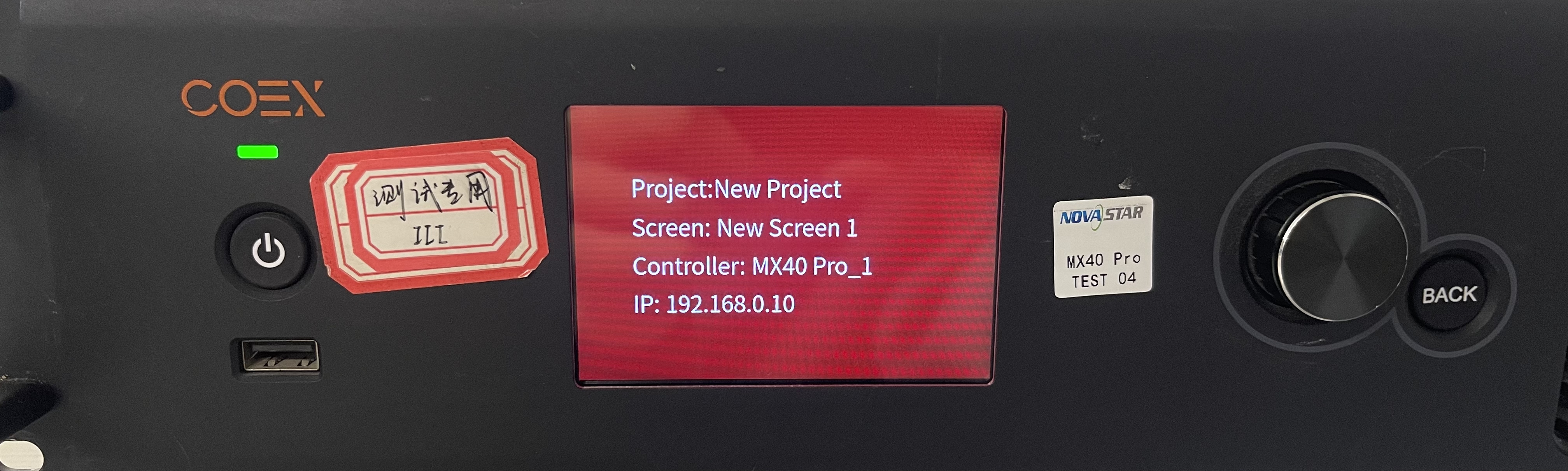
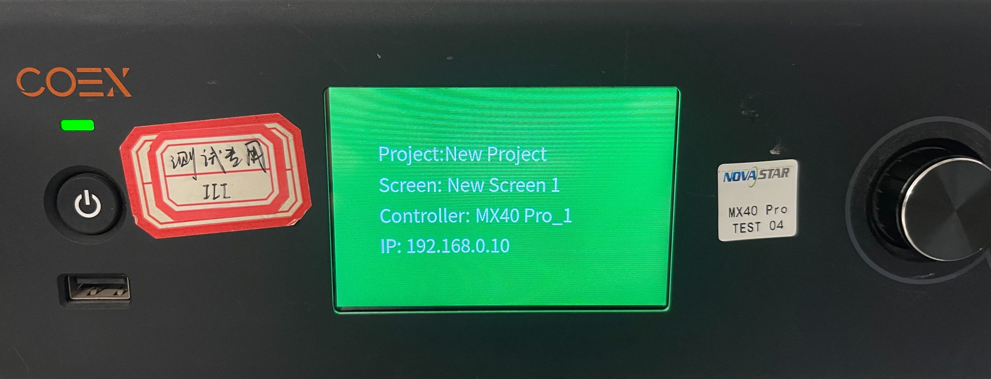
¶ Controller Identify
Customizable background color for controller identify. When there are many COEXs, using controller identify to quickly find one of them.
Choose and right-click the controller that need to be customize background color on the project list, then click the "Controller Finder", then choose a color.
After this operation, the LCD panel of this controller will become the color you choose, and the project, screen, controller and IP will be show on the panel.
We consistently enhance and refine the content of our Wiki articles.
If you find any mistakes or errors, please contact us.
Your continuous feedback and support will help us further improve our products and content.